
Electronic line shaft with phased lock loop filtering and predicting

a phase lock loop and phase shift technology, applied in the direction of dynamo-electric converter control, program control, instruments, etc., can solve the problems of phase shift between drives, mechanical shaft systems are cumbersome and difficult to reconfigure, and introduce additional network-type propagation delays

Active Publication Date: 2007-01-18
ROCKWELL AUTOMATION TECH
View PDF1 Cites 14 Cited by
  • Summary
  • Abstract
  • Description
  • Claims
  • Application Information

AI Technical Summary

Benefits of technology

[0011] Thus it is one object of at least one embodiment of the invention to accommodate network delay and jitter with minimal position phase error.
[0013] Thus it is another object of at least one embodiment of the invention to provide a simple implementation of a predictor in the form of a phase locked loop.
[0019] It is thus another object of at least one embodiment of the invention to allow a simple method of creating virtual gear boxes on an electronic line shaft.
[0021] It is thus another object of at least one embodiment of the invention to provide a simple electronic system for smoothing velocity and position changes of the line shaft.
[0024] It is thus another object of at least one embodiment of the invention to provide a simple method of extracting velocity from a position signal through the use of a phase lock loop.
[0026] It is thus another object of at least one embodiment of the invention to provide a simple method of predicting a position in the future through the introduction of a delay in the feedback loop of the phase lock loop.

Problems solved by technology

Over time, the mechanical line shaft may wear, causing phase shift among the drives.
Mechanical shaft systems are also cumbersome and difficult to reconfigure.
While the electronic signals transmitted from the master reference or virtual master reference to each of the servant drives propagate at an extremely high rate, it is not instantaneous and thus there may be some phase lag at servant motor drives that are displaced spatially or electronically from the master reference.
This problem is particularly acute for networks which provide simplicity in connecting motor drives, but which introduce additional network-type propagation delays.
This approach of anticipating network delay, however, is not always successful because of a variation in the delay depending on network traffic and other factors.
Further, for systems that work at different rotational speeds, advancing the cylinder positions, for example by adjusting the encoders or the like, for a given speed will produce phase errors for lower speeds where the propagation delay results in an effectively smaller phase advance.

Method used


Image

  • Electronic line shaft with phased lock loop filtering and predicting
  • Electronic line shaft with phased lock loop filtering and predicting
  • Electronic line shaft with phased lock loop filtering and predicting

Examples


Embodiment Construction

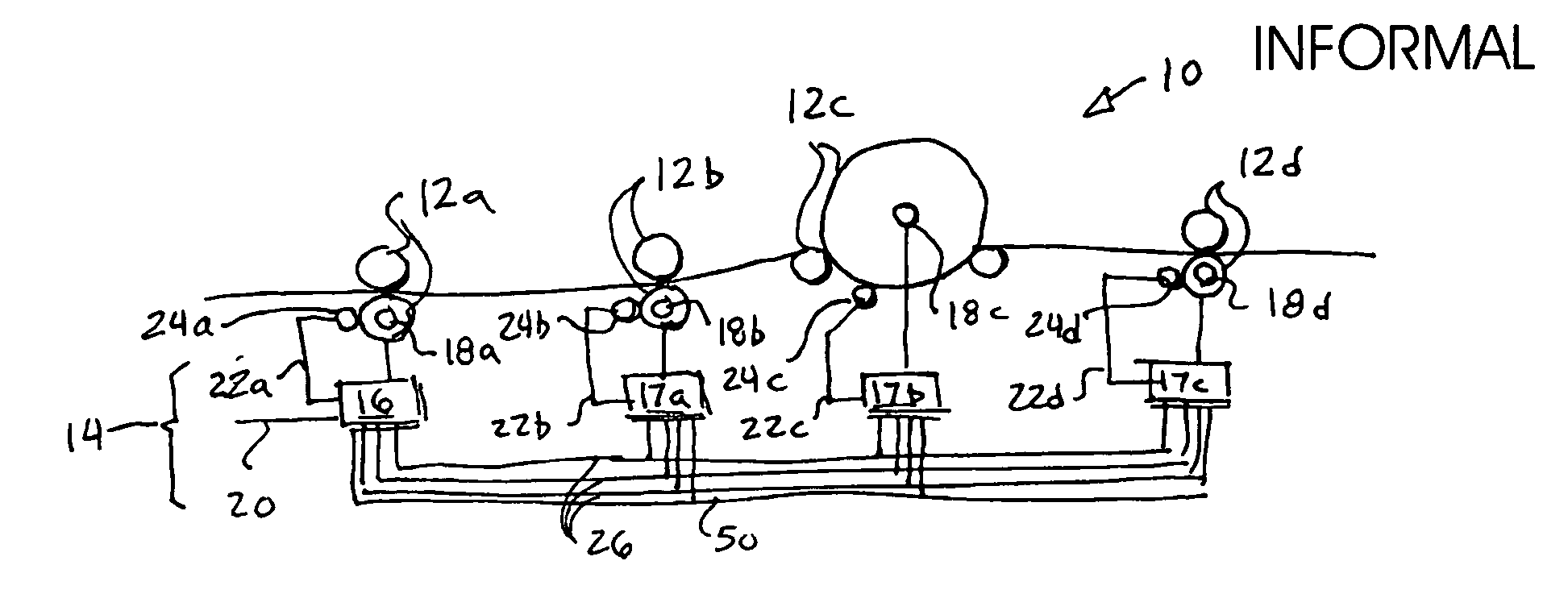
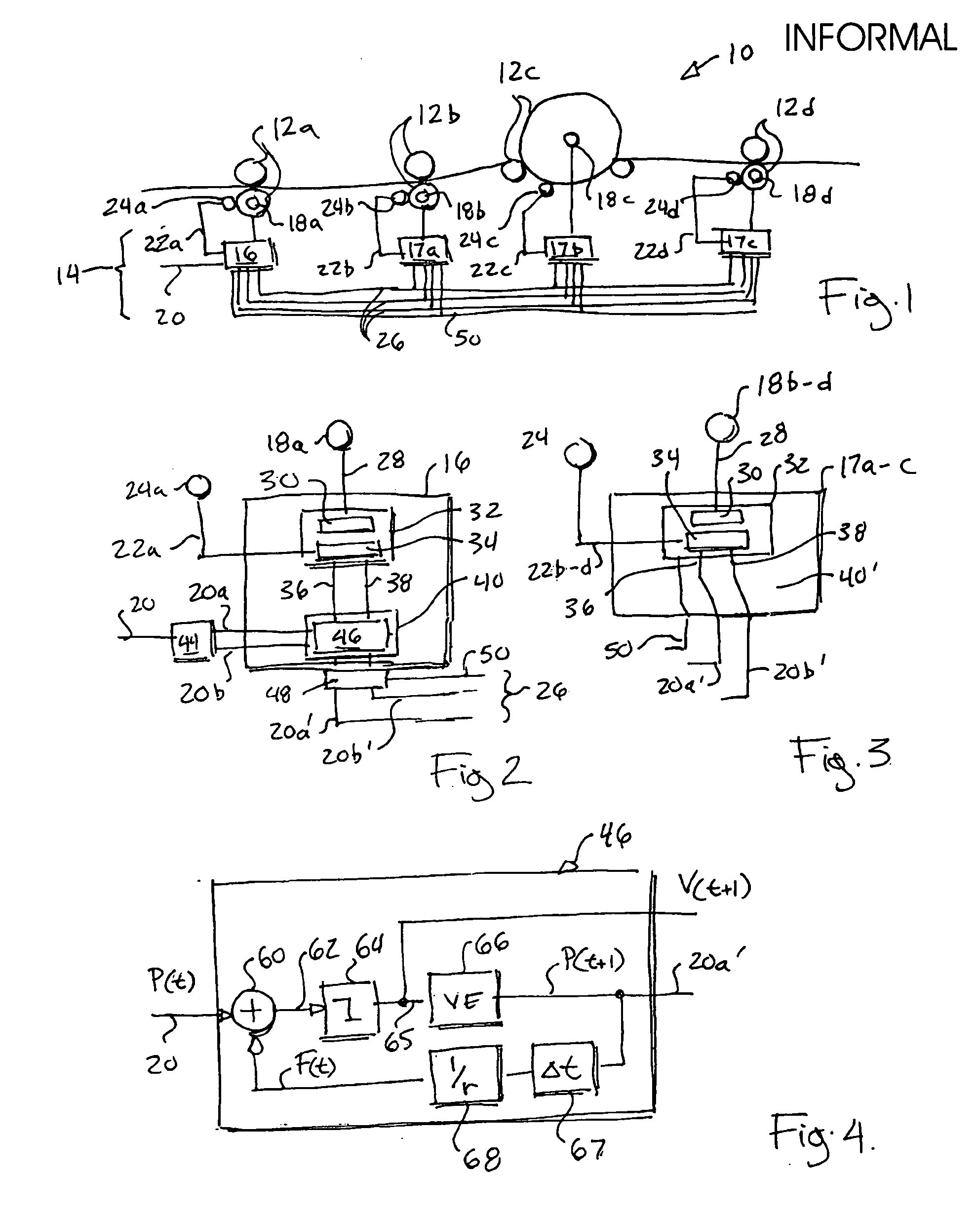
[0036] Referring now to FIG. 1, a printing press 10 may employ a number of printing cylinder pairs 12a-12d, synchronized with each other by means of an electronic line shaft 14.

[0037] The electronic line shaft 14 includes a master controller 16 associated with and possibly controlling a motor 18a connected to the cylinder pair 12a. The master controller 16 receives a command signal 20 and a feedback signal 22a, the latter being either position or position and velocity, to provide the necessary position control of the cylinder pair 12a. The feedback signal 22a is typically provided by a position encoder 24a. Command signal 20 may be a digital word representing incremental encoder position or the like or other feedback devices providing for a position output. The command signal 20 may be derived from a circuit providing a virtual encoder output simulating a reference rotating shaft or from an actual reference encoder attached to a shaft that is minimally disturbed, such as a shaft on...


PUM


Abstract

An improved electronic line shaft provides for a predictor sending predicted position and / or velocity values to servant drives that may be later strobed in by high speed low-latency strobe signals to eliminate network jitter and delay. The predictor may be implemented as a phase lock loop, providing filtering of a master encoder signal together with flexible electronic gear ratio adjustments and other desired control refinements.

Description

CROSS-REFERENCE TO RELATED APPLICATIONS [0001] This application is a continuation-in-part of application Ser. No. 11 / 141,596 filed May 13, 2005, incorporated by reference herein.STATEMENT REGARDING FEDERALLY SPONSORED RESEARCH OR DEVELOPMENT BACKGROUND OF THE INVENTION [0002] The present invention relates to electronic line shafts in which servo driven motors simulate a mechanically continuous shaft and, in particular, to an electronic system for improving electronic line shaft operation. [0003] Many industrial processes require a mechanical line shaft with intermediate gear boxes or the like to maintain precise phase or position among a number of driven structures. For example, in a printing press, each color must be precisely overlaid on the previous color to hold registration and this may be done by a mechanical line shaft joining each of the print cylinders. [0004] Over time, the mechanical line shaft may wear, causing phase shift among the drives. Mechanical shaft systems are a...

Claims


Application Information

Patent Timeline
Patent Type & Authority Applications(United States)
IPC IPC(8): H02P7/00
CPCB41F13/004B41P2213/734G05B19/232G05B2219/37181H03L7/08G05B2219/45187G05B2219/50218H02P5/46H02P5/52G05B2219/37436
Inventor WIRTZ, STEVEN MICHAELREHM, THOMAS J.
Owner ROCKWELL AUTOMATION TECH
Learn More