
Fault tolerant computer controlled system

Inactive Publication Date: 2007-08-28
SUPERCOMPUTING SYST
View PDF9 Cites 21 Cited by
  • Summary
  • Abstract
  • Description
  • Claims
  • Application Information

AI Technical Summary

Benefits of technology

[0007]Hence, it is a general object of the invention to provide a method and system of the type mentioned above that is easier to implement, to analyze and to test while maintaining a low risk of failure.
[0014]In normal operation, each data receiver receives every data item at least twice through separate communication links. Even though this requires additional bandwidth, it has the advantage that no re-routing of data items is required if a fault in a communication link occurs, i.e. the flow of information does not have to be rearranged when a failure occurs, which makes the system more reliable and easier to analyze and to test. It is easy to predict what kind of failures the system is able to handle and there is no need to test all possible combinations of potential failures.
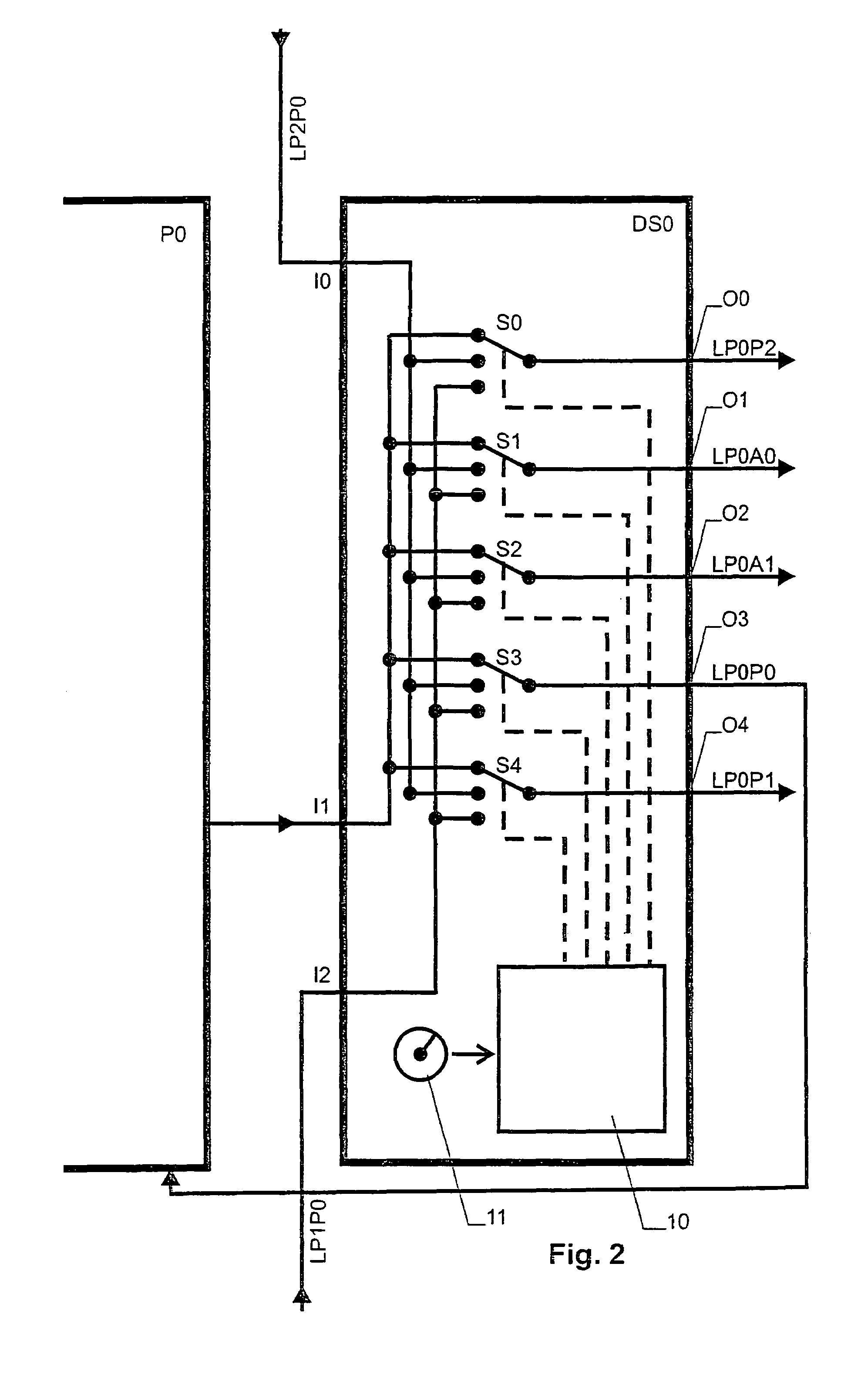
[0026]Hence, in this aspect, the switching assembly is divided into a plurality of switching units, wherein each switching unit is connected via at least two switch communication links to other switching units and wherein each data receiver is connected to at least two different switching units. Subdividing the switching assembly in this way provides improved performance if any one of the switching units should fail. In an advantageous embodiment, exactly one switching unit is attributed to each data source and, preferably, one input of each switching unit is connected an output of its data source.
[0033]In this aspect, a synchronous transmission scheme is used where repetitive time windows are attributed to each data source. In each time window, the switching assembly connects all receiver communication links to the data source attributed to the time window. This again leads to an increase of required bandwidth, but it helps to keep the system simple. In addition to this, it prevents a faulty data source from jamming a receiver communication link continuously because each data source only has access to the communication link during its data window. If the switching assembly is divided into switching units connected as mentioned above, the same scheme can be used for preventing a jamming of the switch communication links.
[0034]In another advantageous embodiment, a unique key is attributed to each data source. The data items sent by each source are digitally signed by the corresponding key, and the signature is checked upon receipt of the data item in a data receiver. Using such a signature scheme provides a further possibility for detecting corrupted messages.

Problems solved by technology

As computer systems gain increasing significance in many applications of human life, their reliability becomes more and more important because a failure may have dire consequences, including injury or casualties.
Typical “mean times between failure” of electronic computers are in the order of 10 4 hours, which is unacceptably high for critical applications.
This type of system is unable to transmit data items upon failure of a communication link.
As systems of this type may contain a large number of computers and receivers and even a larger number of communication links, the required steps for re-routing the data items upon failure of a communication link may become fairly complex.
Also, analysis and testing of the system for all possible failures and re-routing configurations becomes very complicated and expensive if not impossible.

Method used


Image

  • Fault tolerant computer controlled system
  • Fault tolerant computer controlled system
  • Fault tolerant computer controlled system

Examples


Embodiment Construction

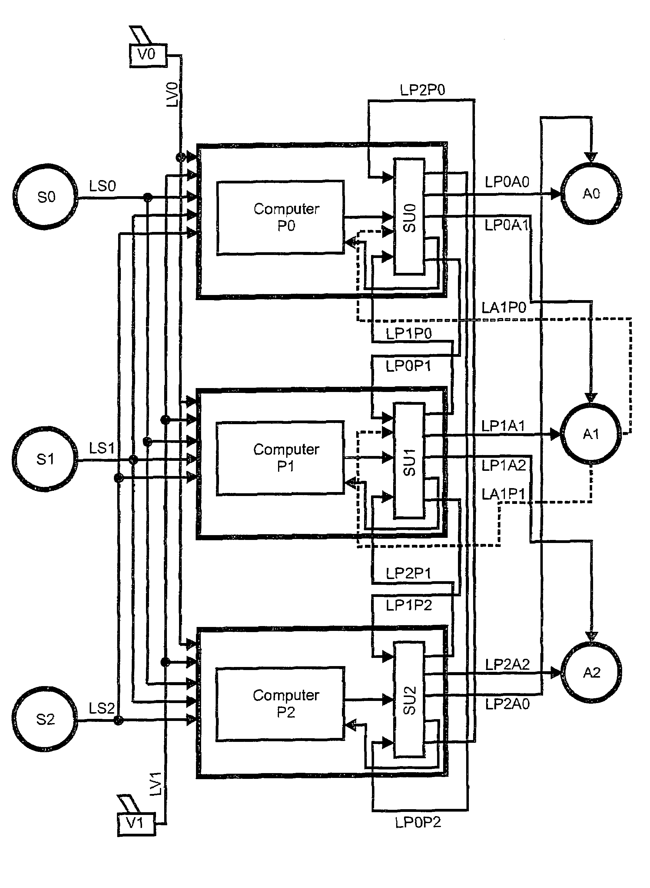
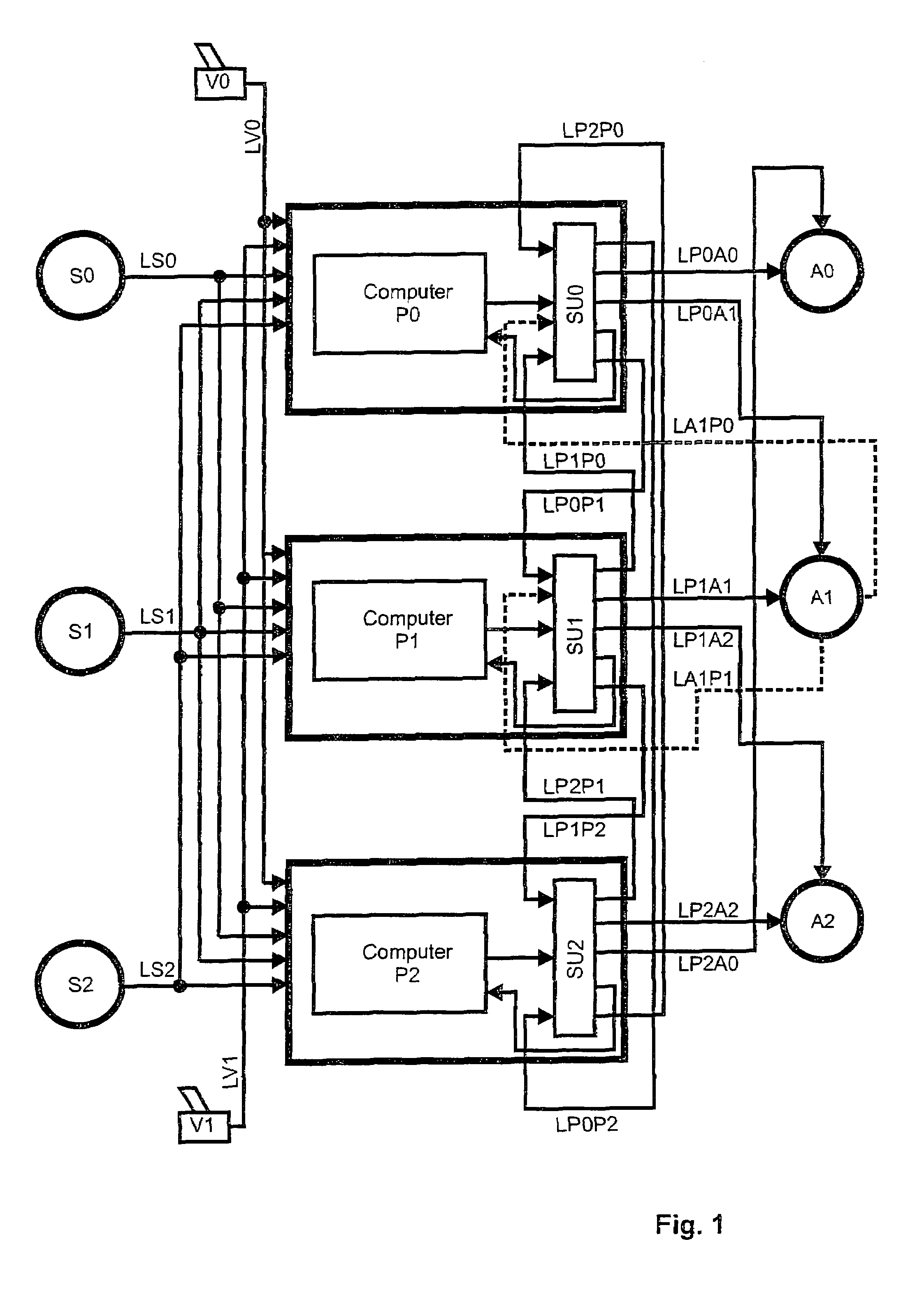
[0045]The system of FIG. 1 is operated by three redundant computers P0, P1 and P2, which process the signals from three sensors S0, S1 and S2 and two input devices V0, V1 and control three actuators A0, A1 and A1. One switching unit SU0, SU1, SU2 is attributed to each computer.

[0046]In a specific embodiment, the system shown here may control a vehicle, where the sensors S0, S1, and S2 e.g. measure the vehicle's position, attitude and / or velocity, the input devices V0 and V1 are controls operated by the user, and A0, A1 and A2 are actuators controlling the vehicle's drive and steering mechanism.

[0047]For reliability reasons, there are at least two redundant sensors for measuring each parameter used by the computers P0, P1, P2, and the input devices LV0, LV1 are provided in duplicate.

[0048]The computers P0, P1 and P2 generate commands for the actuators A0, A1, A2 as a function of the input provided by the sensors S0, S1 and S2 and the input devices LV0, LV1 as well as of state variabl...


PUM


Abstract

An error tolerant computer controlled system comprises several computers working redundantly and controlling actuators based on signals from sensors and input devices. Each data item emitted by each computer is simultaneously sent through differing communication paths to each actuator, such that in normal operation each actuator receives each data item through several paths. This system continues to function properly even in case of a failure without requiring any re-routing of the data items, which makes it easier to design, analyze and test and thereby increases its reliability.

Description

CROSS REFERENCE TO RELATED APPLICATIONS[0001]This application claims the priority of European patent application 03001308.0, filed Jan. 23, 2003, the disclosure of which is incorporated herein by reference in its entirety.BACKGROUND OF THE INVENTION[0002]The present invention relates to a fault tolerant computer controlled system as it can e.g. be used for controlling a vehicle or other critical device.[0003]As computer systems gain increasing significance in many applications of human life, their reliability becomes more and more important because a failure may have dire consequences, including injury or casualties. Example of such computer systems are vehicle guidance or control systems, such as train guidance or aircraft control systems, as well as medical systems.[0004]Typical “mean times between failure” of electronic computers are in the order of 10 4 hours, which is unacceptably high for critical applications. Hence, it has been common practice to use several computers in a p...

Claims


Application Information

Patent Timeline
IPC IPC(8): G06F11/00B64C13/00G05B9/03G06F11/18
CPCG05B9/03G06F11/184
Inventor SAILER, THOMAS MICHAEL
Owner SUPERCOMPUTING SYST
Learn More