
Digital phase locked loop, method for controlling a digital phase locked loop and method for generating an oscillator signal

a technology of digital phase and loop, applied in the direction of pulse automatic control, pulse technique, counting chain pulse counter, etc., can solve the problem that the signal applied to the feedback input of the phase detector is not constant over a relatively long period of time, and achieve the effect of sufficient stability

Inactive Publication Date: 2007-01-11
INFINEON TECH AG
View PDF14 Cites 11 Cited by
  • Summary
  • Abstract
  • Description
  • Claims
  • Application Information

AI Technical Summary

Benefits of technology

[0012] The precisely defined jitter or additional jitter within the frequency setting word prevents a signal which is applied to the feedback input of the phase detector from being temporally constant over a relatively long period of time and the phase detector thus no longer generates a beat in the case of an integer multiple of the frequency of the reference signal. In other words, as a result of the invention, the phase detector generates an error signal which is not constant over time and is thus processed using a plurality of quantization stages in the phase detector.
[0013] The result is that a digital phase locked loop in accordance with the invention has sufficient stability even in the case of output frequencies that correspond to an integer multiple of a reference frequency.
[0014] In order to control a digital phase detector, a frequency setting word is thus supplied to a frequency divider in a feedback path of the digital phase locked loop, the setting word changing over between at least two values. This prevents the feedback signal being at a frequency that is constant over a relatively long period of time.

Problems solved by technology

The data word is therefore configured so that the sigma-delta modulator always generates jitter in the frequency setting word during operation, with the result that the signal which is applied to the feedback input of the phase detector is not constant over a relatively long period of time.

Method used


Image

  • Digital phase locked loop, method for controlling a digital phase locked loop and method for generating an oscillator signal
  • Digital phase locked loop, method for controlling a digital phase locked loop and method for generating an oscillator signal
  • Digital phase locked loop, method for controlling a digital phase locked loop and method for generating an oscillator signal

Examples


Embodiment Construction

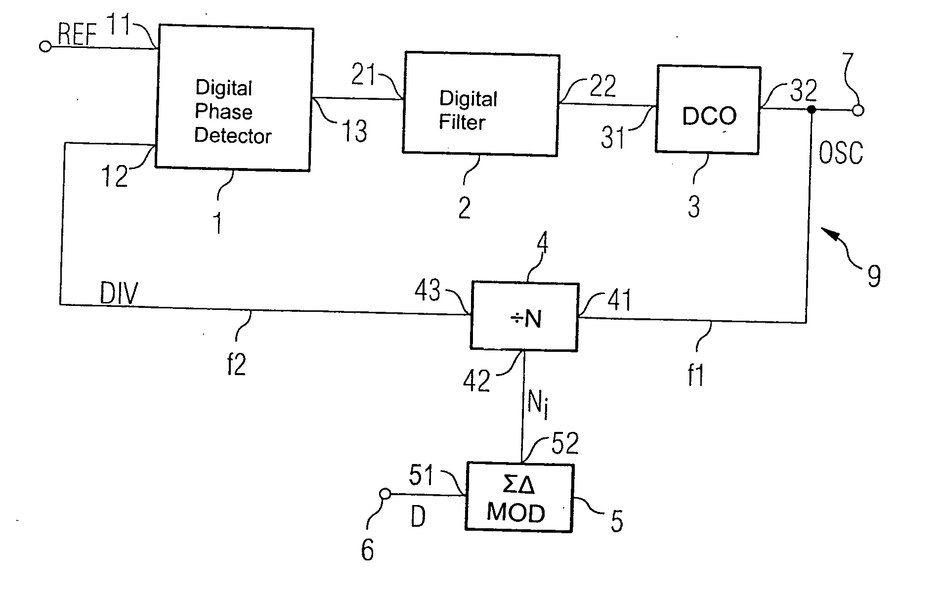
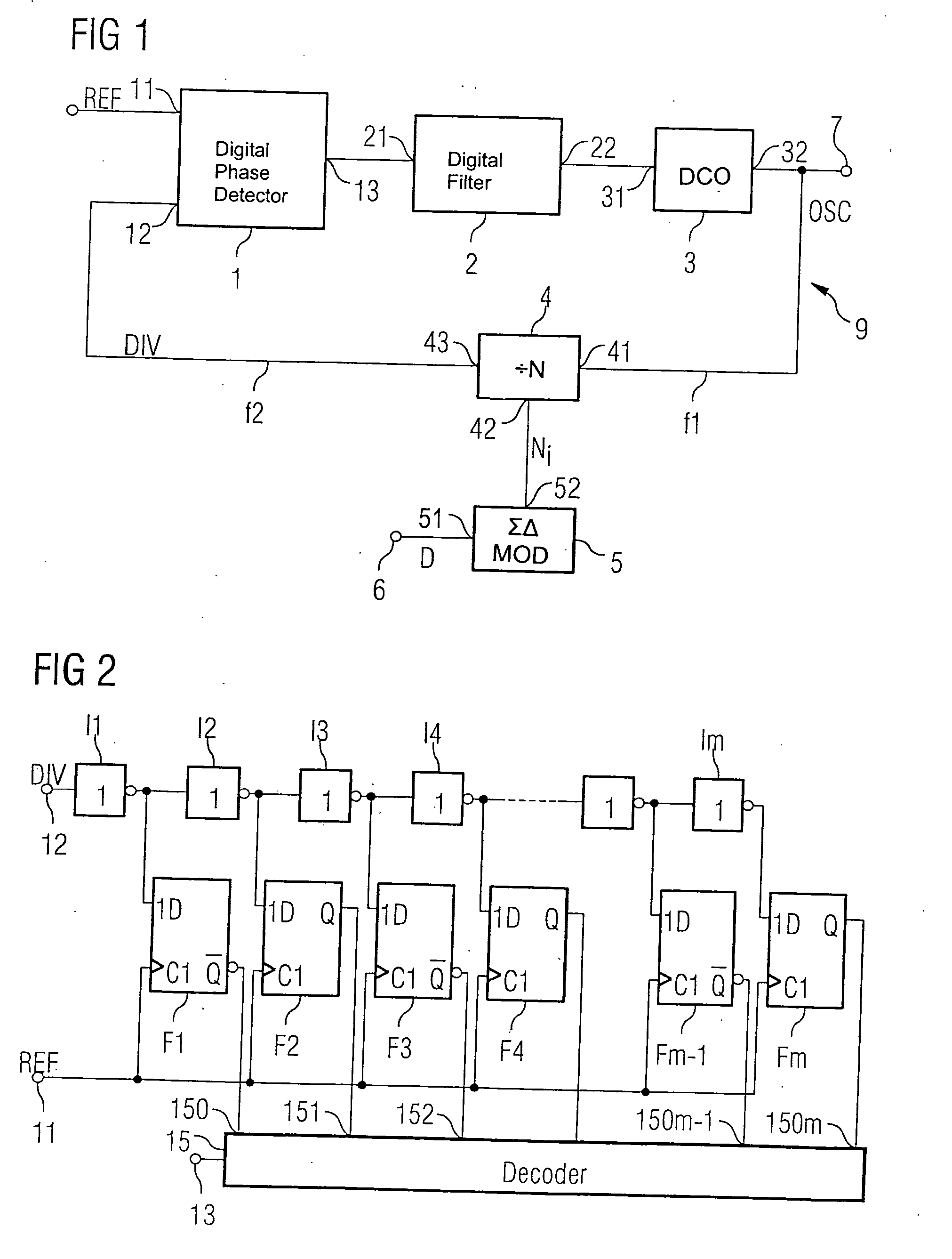
[0023]FIG. 1 shows a block diagram of a digital phase locked loop 9 according to one embodiment of the invention. In this exemplary embodiment, the digital phase locked loop 9 is implemented in the form of an integrated circuit in a semiconductor body. The control loop 9 comprises a forward path having a digital phase detector 1, a digital filter 2 and a digitally controllable oscillator (DCO) 3.

[0024] The digital phase detector 1 has a reference input 11 and a feedback input 12. The output 13 of the digital phase detector 1 is connected to an input 21 of the digital filter 2. The output 22 of the digital filter 2 is connected to the actuating input 31 of the controllable oscillator 3. The output signal from the controllable oscillator 3 at the output 32 of the latter is, on the one hand, supplied to the output 7 of the digital phase locked loop and, on the other hand, is applied to the input 41 of a frequency divider 4 in a feedback path of the control loop.

[0025] The frequency d...


PUM


Abstract

A digital phase locked loop includes a digital phase detector, a downstream digital filter and an oscillator. In addition, a frequency divider resides in a feedback path and has an actuating input for setting a divider ratio, the input of which is connected to the oscillator and the phase detector. The phase locked loop comprises a sigma-delta modulator having a data input for supplying a data word and having an actuating output for supplying a frequency setting word to the actuating input of the frequency divider. The data word is configured such that the sigma-delta modulator generates jitter in the frequency setting word, with the result that the signal which is applied to the feedback input of the phase detector is not constant over a relatively long period of time.

Description

REFERENCE TO RELATED APPLICATIONS [0001] This application claims the benefit of the priority date of German application DE 10 2005 030 356.0, filed on Jun. 29, 2005, the contents of which are herein incorporated by reference in their entirety. FIELD OF THE INVENTION [0002] The invention relates to a digital phase locked loop, to a method for controlling a digital phase locked loop, and to a method for generating an oscillator signal. BACKGROUND OF THE INVENTION [0003] Increasing miniaturization in the field of mobile radio, in particular in mobile communication devices, is resulting in the development of radiofrequency assemblies with a very high integration density. Many of the radiofrequency assemblies required have, in the meantime, been produced in the form of integrated circuits in semiconductors using different process technologies. In this case, easy portability of the various radiofrequency assemblies to ever finer semiconductor structures is increasingly strived for, a proc...

Claims


Application Information

Patent Timeline
IPC IPC(8): H03L7/085
CPCH03K23/667H03L7/091H03L2207/50H03L7/099H03L7/1976H03L7/093
Inventor MAYER, THOMASHERZINGER, STEFANNEURAUTER, BURKHARDMARZINGER, GUNTER
Owner INFINEON TECH AG
Learn More