
Method and system of MR imaging with reduced FSE cusp artifacts

a technology of mr imaging and cusp artifacts, applied in the field of parallel imaging and image reconstruction, can solve the problems of affecting image quality, signal collapse upon itself within the image, and general linear gradient fields, so as to reduce ghosting and reduce the adverse effects of located areas

Active Publication Date: 2007-01-11
GENERAL ELECTRIC CO
View PDF3 Cites 19 Cited by
  • Summary
  • Abstract
  • Description
  • Claims
  • Application Information

AI Technical Summary

Benefits of technology

[0021] Therefore, in accordance with one aspect, the invention includes an apparatus having a computer programmed to reduce artifacts associated with gradient null locations in MR imaging. The computer is programmed to define one or more gradient null locations and determine receive coil sensitivity at the one or more gradient null locations. The computer is further programmed to acquire MR data from multiple receive coils in an FOV and weight the MR data based on the determined receive coil sensitivity, respectively. The computer is also programmed to reconstruct an image by combining the weighted MR data from the multiple receive coils, wherein the reconstructed image has reduced artifacts from the one or more gradient null locations
[0023] In accordance with another aspect of the invention, an MR imaging apparatus includes a plurality of gradient coils positioned about a bore of a magnet to impress a polarizing magnetic field. An RF transceiver system and an RF switch are controlled by a pulse module to transmit and receive RF signals to and from an RF coil assembly to acquire MR images. The MR imaging apparatus also includes a computer programmed to acquire coil sensitivity data of each coil of a coil array to at least one gradient null location and acquire imaging data from an FOV with the coil array. The computer is further programmed to calibrate the imaging data with the coil sensitivity data to reduce gradient null artifacts in the imaging data and reconstruct an image of the FOV from the imaging data that is substantially free of gradient null artifacts
[0025] According to a further aspect, the invention is embodied in a method of MR imaging with reduced ghosting. The method includes locating areas of gradient field nulling that produce adverse effects in reconstructed MR images and acquiring MR data. The method further includes determining a true-like object magnetization of the acquired MR data by reducing the adverse effects of the located areas of gradient field nulling and reconstructing an image from the true-like object magnetization.

Problems solved by technology

In practice, however, the gradient fields are generally only approximately linear within a limited volume.
These points of near-zero slope are commonly referred to as gradient nulls and can adversely affect image quality.
That is, if magnetization is present at such a location and the transmit RF field is sufficiently large at that location to excite the magnetization, the resulting signal can cause artifacts.
Moreover, since the gradient field at a gradient null location provides almost no spatial encoding, the signal collapses upon itself within the image.
Moreover, if the signal does not directly alias into the imaging volume, system hardware instabilities, such as in the gradient or RF coils, eddy currents, or k-space modulation resulting from refocusing or different magnetization pathways in some echo train pulse sequences can cause ghosting of the intense signal in the phase or slice encoding directions.
While a number of MR imaging techniques can be impacted by gradient nulls, fast spin echo (FSE) imaging is particularly prone to gradient null ghosting.
While it is recognized that improved gradient coil design would help reduce the impact of gradient nulls, such a solution would require retrofitting existing MR scanners with new hardware, which could be cost-prohibitive.
A drawback of an RF blanket, however, is that to be effective, the RF blanket must be precisely positioned within the imaging volume.
Acquiring pre-scan knowledge of a gradient null location can be time consuming and negatively affect subject throughput.
Not only would such a placement of the blanket be uncomfortable for some subjects, but be impractical for near-head spine scans.
As such, it is recognized that spoilers on any axis would be ineffective at suppressing the signal from the gradient null.
Such an approach is believed impractical.
In other words, there is no guarantee that the artifact will be less severe at the new gradient null location than at the original location.
However, this approach may not be practical for many applications because of motion artifacts.
However, simply increasing the FOV does not prevent ghosting of the signal from overlaying the reconstructed image.
Further, simply repositioning the subject to shift the relative location of the artifact is believed ineffective and, moreover, generally inconvenient.
However, this assumption is inapplicable to artifacts arising from gradient nulls.
However, this technique is not practical for those instances where the signal from the gradient null (the signal that would be canceled) is aliased into the imaging volume.
While gradient null artifacts are not specifically addressed with this approach; nevertheless, the technique is complex and computationally intensive.

Method used


Image

  • Method and system of MR imaging with reduced FSE cusp artifacts
  • Method and system of MR imaging with reduced FSE cusp artifacts
  • Method and system of MR imaging with reduced FSE cusp artifacts

Examples


Embodiment Construction

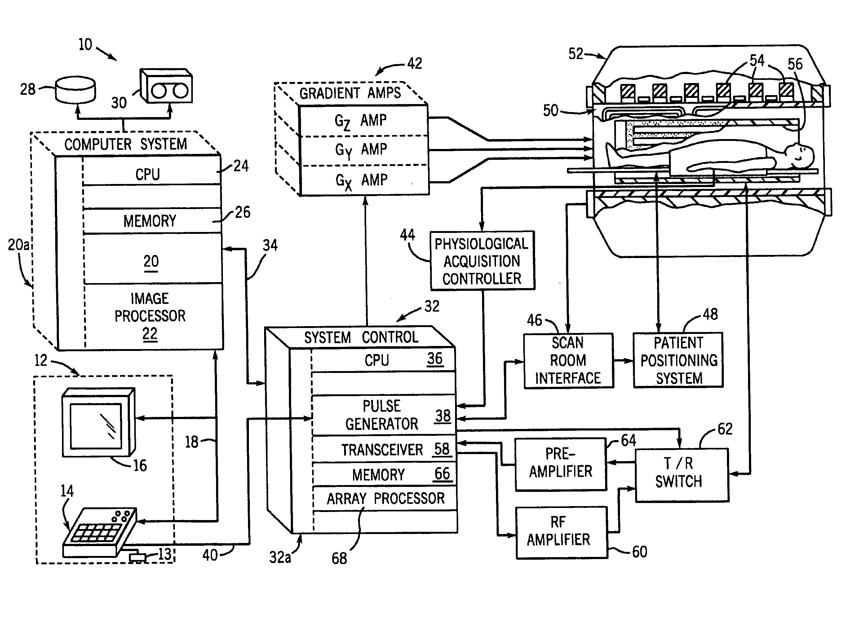
[0042] Referring to FIG. 1, the major components of a preferred MR imaging system 10 incorporating the present invention are shown. The operation of the system is controlled from an operator console 12 which includes a keyboard or other input device 13, a control panel 14, and a display screen 16. The console 12 communicates through a link 18 with a separate computer system 20 that enables an operator to control the production and display of images on the display screen 16. The computer system 20 includes a number of modules which communicate with each other through a backplane 20a. These include an image processor module 22, a CPU module 24 and a memory module 26, known in the art as a frame buffer for storing image data arrays. The computer system 20 is linked to disk storage 28 and tape drive 30 for storage of image data and programs, and communicates with a separate system control 32 through a high speed serial link 34. The input device 13 can include a mouse, joystick, keyboard...


PUM


Abstract

Coil sensitivity of a receive coil to a gradient null location is measured and, from the measurements, a coil calibration value is determined and used to modify the MR data acquired with that receive coil to reduce the adverse effects of gradient nulling on MR images. Coil sensitivity values are determined for each coil of a coil array and the data for each coil is respectively weighted. An image that is substantially free of gradient null artifacts or ghosting is then reconstructed from the weighted data.

Description

BACKGROUND OF THE INVENTION [0001] The present invention relates generally to magnetic resonance (MR) imaging and, more particularly, to a method and system of parallel imaging and image reconstruction that reduces the adverse effects of gradient nulls on a reconstructed image. [0002] When a substance such as human tissue is subjected to a uniform magnetic field (polarizing field B0), the individual magnetic moments of the spins in the tissue attempt to align with this polarizing field, but precess about it in random order at their characteristic Larmor frequency. If the substance, or tissue, is subjected to a magnetic field (excitation field B1) which is in the x-y plane and which is near the Larmor frequency, the net aligned moment, or “longitudinal magnetization”, Mz, may be rotated, or “tipped”, into the x-y plane to produce a net transverse magnetic moment Mt. A signal is emitted by the excited spins after the excitation signal B1 is terminated and this signal may be received a...

Claims


Application Information

Patent Timeline
IPC IPC(8): G01V3/00
CPCG01R33/5611G01R33/56518G01R33/5617G01R33/5615
Inventor KING, KEVIN F.KINKS, RICHARD S.
Owner GENERAL ELECTRIC CO
Learn More