
Method of manufacturing honeycomb structure

Inactive Publication Date: 2006-12-28
NGK INSULATORS LTD
View PDF12 Cites 12 Cited by
  • Summary
  • Abstract
  • Description
  • Claims
  • Application Information

AI Technical Summary

Benefits of technology

[0010] The present invention has been developed in view of the above-described problem, and an object is to provide a honeycomb structure manufacturing method which is capable of efficiently and inexpensively manufacturing a honeycomb structure for preferable use in a filter for trapping particulates in an exhaust gas or the like by use of a long-life grinding member whose satisfactory grinding performance is retained for a long time.
[0021] As described above, according to the present invention, there is provided a honeycomb structure manufacturing method which is capable of efficiently and inexpensively manufacturing a honeycomb structure for preferable use in a filter for trapping particulates in an exhaust gas or the like by use of a long-life grinding member whose satisfactory grinding performance is retained for a long time.

Problems solved by technology

The honeycomb structure for use in such purpose has a problem that a temperature distribution in the honeycomb structure becomes non-uniform owing to a rapid temperature change of the exhaust gas or locally generated heat, and cracks are generated in the structure.
In this case, since locally raised temperature cannot be avoided, the cracks are easily generated by a large thermal stress.
This method has a problem that a wearing speed of the grinding member, especially the bonding material is high, the diamond abrasive grains drop off without being substantially worn, a grinding capability degrades, a life of the grinding member as a tool is short, and the member is not advantageous in respect of costs.
However, the grinding member is not necessarily sufficiently satisfactory, because the wearing speed of the bonding material becomes remarkably high on working conditions that an amount, per certain time, of the outer periphery of the coarsely shaped honeycomb structure to be ground by a dry process is large, and a working object is similar to an abrasive as in a case where the outer periphery is worked into the predetermined shape to thereby manufacture the honeycomb structure.

Method used


Image

  • Method of manufacturing honeycomb structure
  • Method of manufacturing honeycomb structure
  • Method of manufacturing honeycomb structure

Examples


example 1

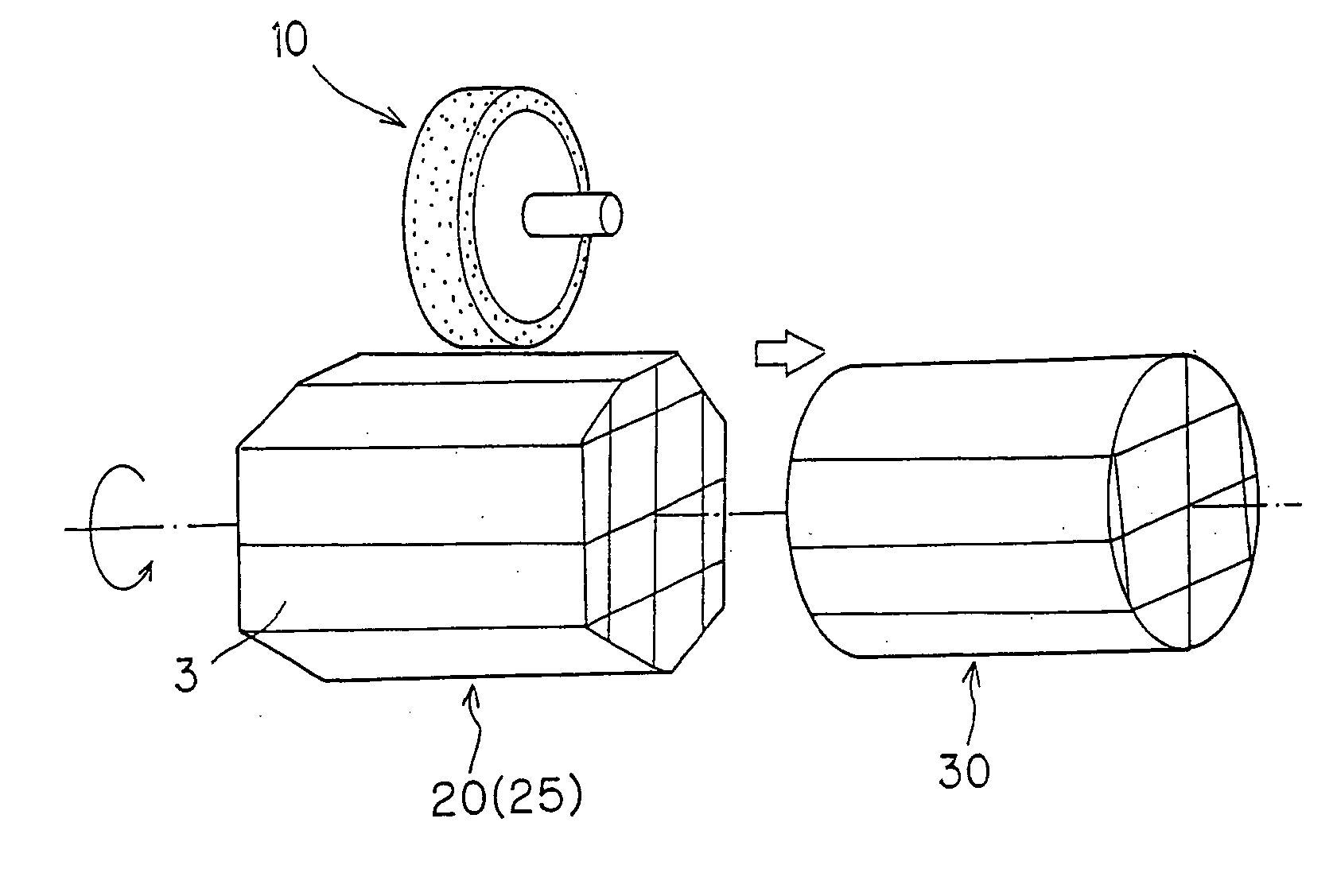
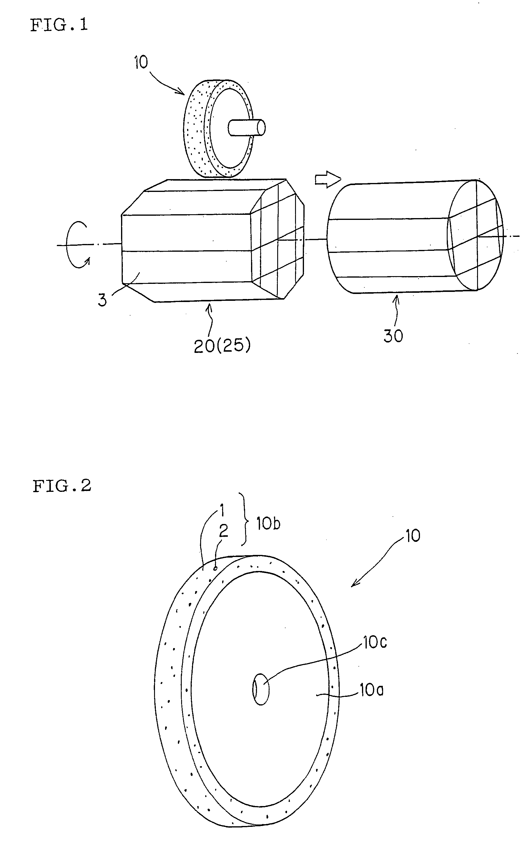
[0051] In grinding of a coarsely shaped honeycomb structure 20 (coarsely worked honeycomb structure 25) shown in FIG. 1 to obtain a honeycomb structure 30, the grinding was performed by operating a wheel grinding member having an outer diameter of 350 mm at a peripheral speed of 120 m / s. The member was constituted by disposing a grinding wheel layer having a thickness of 5 mm on the surface of a circumferential portion of a hub having a diameter of 340 mm and made of carbon steel, stainless steel or the like. In the layer, diamond abrasive grains whose surfaces were coated with Ti having a thickness of 8 to 50 μm were dispersed and fixed in a bonding material made of a metal bond. The grains had a grain size of 100 mesh and a concentration degree of 100 (see Table 5).

examples 2 to 7

, Comparative Examples 1 to 25

[0052] Honeycomb structures were manufactured in the same manner as in Example 1 except that a diamond abrasive grain concentration degree, grain size, grinding wheel peripheral speed, and diamond coating of a grinding member of Example 1 were changed as shown in Tables 1 to 5.

TABLE 1ComparativeComparativeComparativeComparativeComparativeExample 1Example 2Example 3Example 4Example 5Concentration degree70100100100100(100 = 4.4 carats / cm2)Grain size (abrasive10040100180100grain size #)Grinding wheel12012020120160peripheral speed (m / s)Diamond coating (Ti)NoneNoneNoneNoneNone

[0053]

TABLE 2ComparativeComparativeComparativeComparativeComparativeComparativeComparativeExample 6Example 7Example 8Example 9Example 10Example 11Example 12Concentration8090100110120130150degree(100 = 4.4 carats / cm2)Grain size100100100100100100100(abrasivegrain size #)Grinding wheel120120120120120120120peripheralspeed (m / s)DiamondNoneNoneNoneNoneNoneNoneNonecoating (Ti)

[0054]

TABLE 3Co...


PUM


Abstract

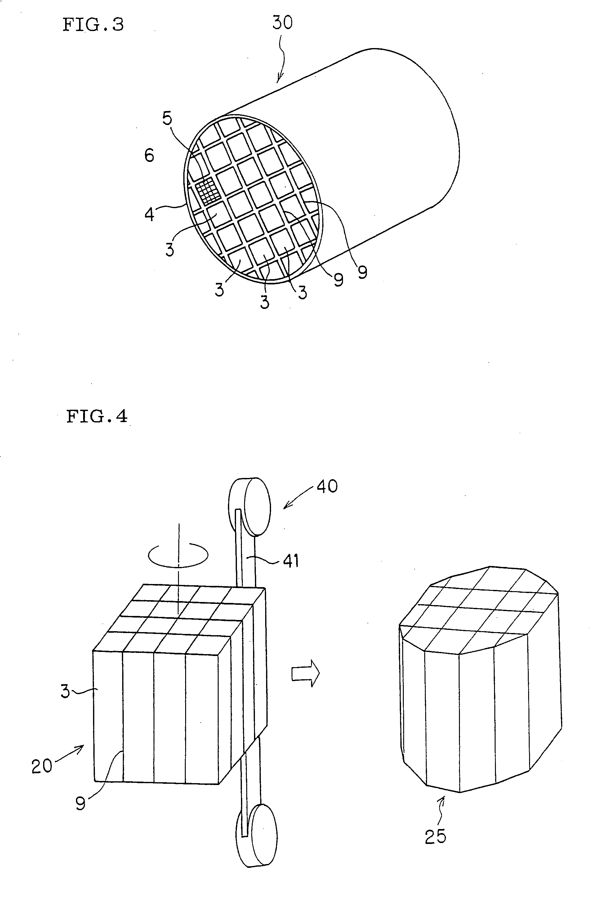
There is disclosed a honeycomb structure manufacturing method which is capable of efficiently and inexpensively manufacturing a honeycomb structure for preferable use in a filter for trapping particulates in an exhaust gas or the like by use of a long-life grinding member whose satisfactory grinding performance is retained for a long time. The method includes the step of: working an outer periphery of a coarsely shaped honeycomb structure 20 made of a porous ceramic by use of a grinding member 10 to obtain a honeycomb structure 30 having a predetermined shape, wherein diamond abrasive grains of the grinding member 10 have a grain size of 40 to 150 mesh (JIS B 4130 standard) and a concentration degree of 80 or more, and the surfaces of the diamond abrasive grains are coated with at least one selected from the group consisting of Ti, Ni, and Cr.

Description

BACKGROUND OF THE INVENTION [0001] 1. Field of the Invention [0002] The present invention relates to a method of manufacturing a honeycomb structure, more particularly to a honeycomb structure manufacturing method which is capable of efficiently and inexpensively manufacturing a honeycomb structure for preferable use in a filter for trapping particulates in an exhaust gas or the like by use of a long-life grinding member whose satisfactory grinding performance is retained for a long time. [0003] 2. Description of the Related Art [0004] A honeycomb structure is used in a filter for trapping particulates in an exhaust gas or the like. The honeycomb structure for use in such purpose has a problem that a temperature distribution in the honeycomb structure becomes non-uniform owing to a rapid temperature change of the exhaust gas or locally generated heat, and cracks are generated in the structure. Especially when the structure is used as a filter (hereinafter sometimes referred to as th...

Claims


Application Information

Patent Timeline
IPC IPC(8): H05B6/80
CPCB24B9/06B24D3/08B24B19/22
Inventor MICHIWAKI, TAISHIITO, YUJIWADA, YUKIHISA
Owner NGK INSULATORS LTD
Learn More