Cryptographic-key-generation communication system
a communication system and cryptographic key technology, applied in the field ofquantumcryptography communication, can solve problems such as the difficulty of stably operating the asymmetric mach zehnder interferometer, and achieve the effect of suppressing the polarization dependency within the receiver and improving the minimum receiving sensitivity
- Summary
- Abstract
- Description
- Claims
- Application Information
AI Technical Summary
Benefits of technology
Problems solved by technology
Method used
Image
Examples
first embodiment
[0055] (First Embodiment)
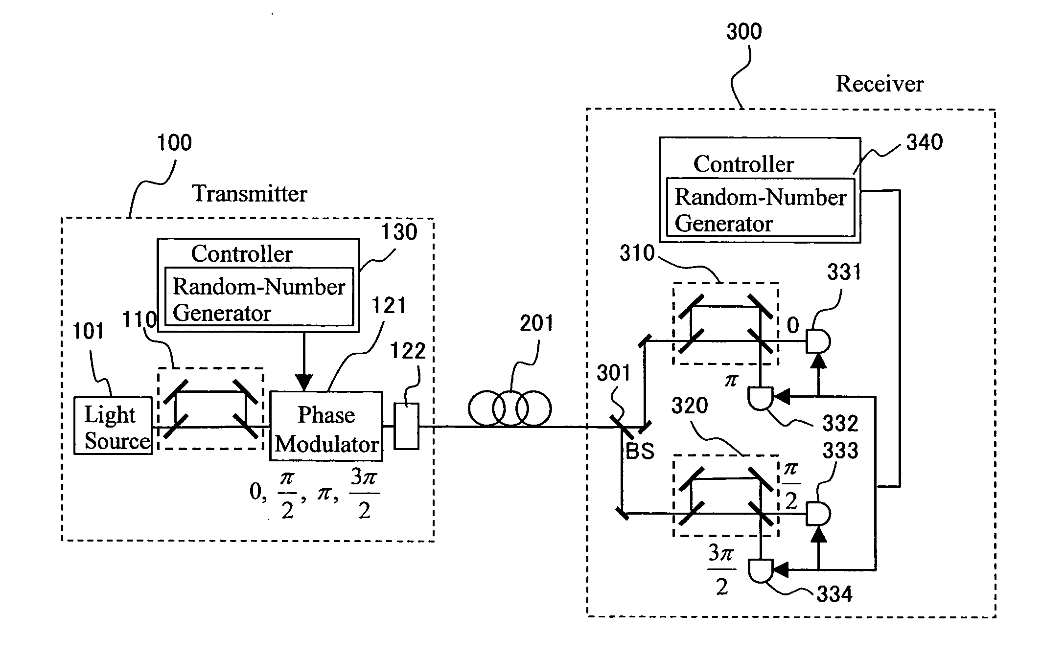
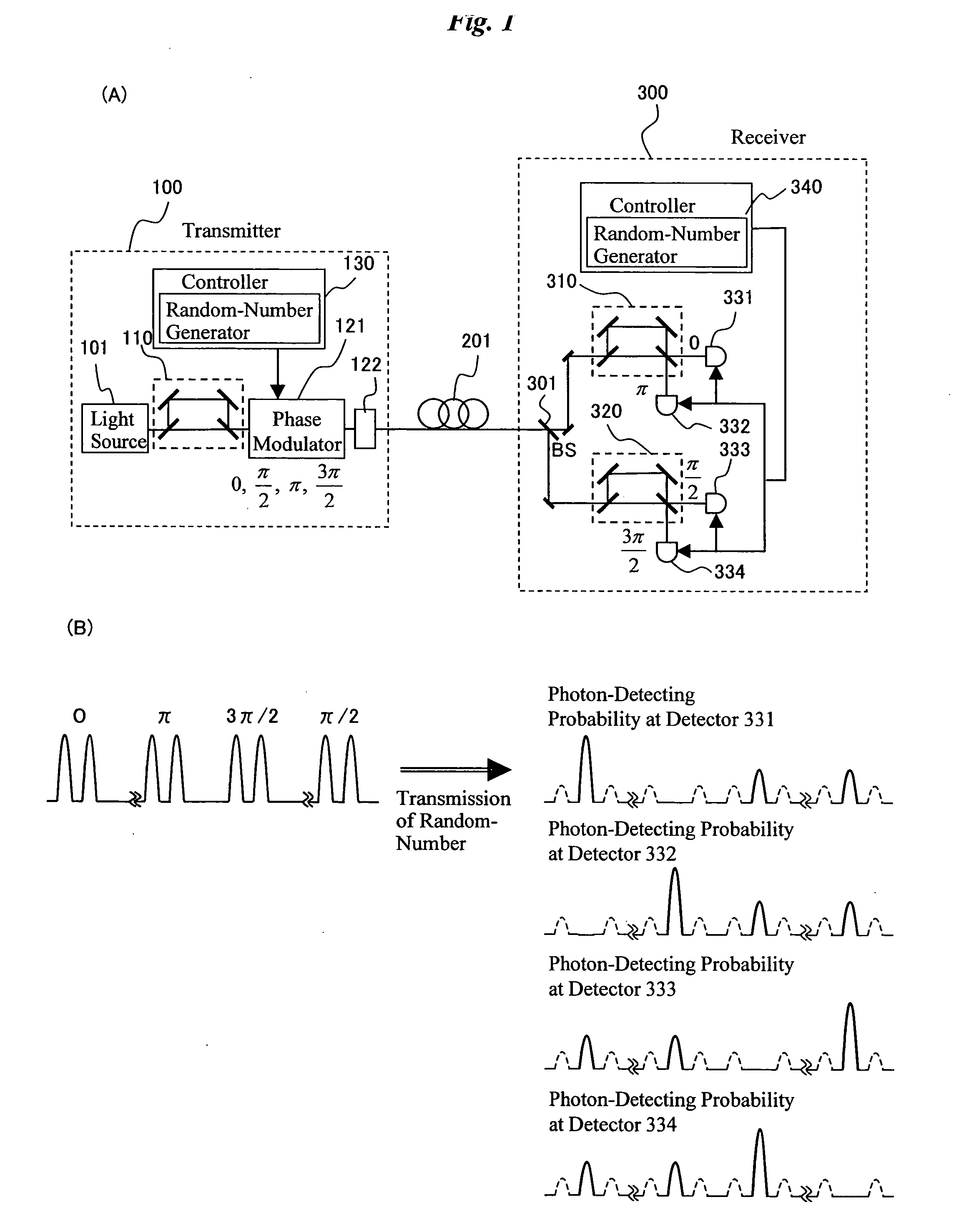
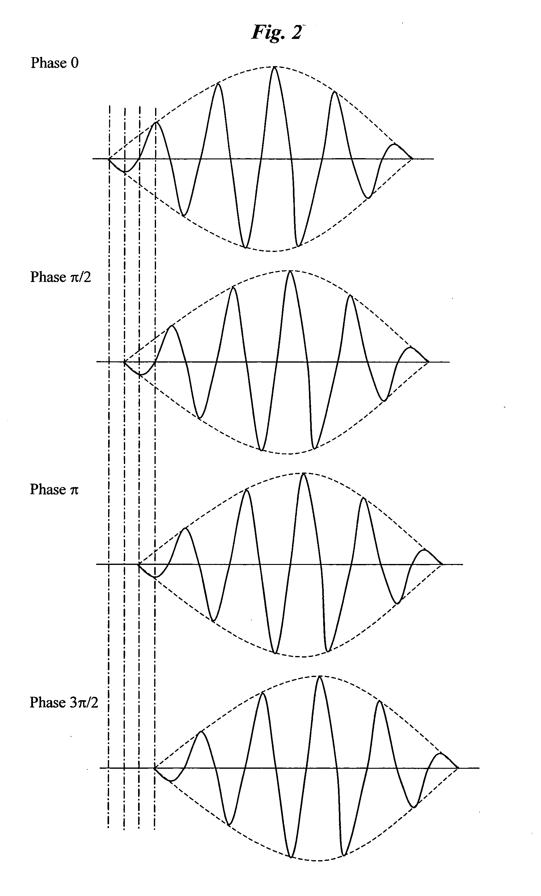
[0056]FIG. 5 is a block diagram showing a communication system according to an embodiment of the present invention. A sender 1 and a recipient 2 communicate with each other through a general line 202. Since the general line 202 is normally easy to eavesdrop, cipher communication is conducted in general. In this situation, it is necessary to share the cryptographic key that can be known by only the sender 1 and the recipient 2. The transmitter 100 generates and transmits the random-number data that is a source for generating the cryptographic key, and the receiver 300 receives the random-number data through the transmission path 201. The description made with reference to FIGS. 1A to 4B is given of the structure and operational principle for transmitting and receiving the random-number data. In this example, the sender 1 and the recipient 2 do not always represent persons, but have broad meaning including a necessary device in the communication, such as compu...
second embodiment
[0081] (Second Embodiment)
[0082] In the first embodiment, optical fibers or PLC is used for the asymmetric Mach Zehnder interferometers 310 and 320, and the phase of the optical path-length difference between two arms is held constant by a temperature control. The optical path-length difference of the asymmetric Mach Zehnder interferometers 310 and 320 must accurately coincide with an amount corresponding to the clock rate, and the method of the first embodiment generally involves difficulty. It is reasonable that the optical delay line is disposed within the interferometer so as to adjust the optical path-length difference. Also, it is difficult to make the phase difference between the two arms of the asymmetric Mach Zehnder interferometer constant by only the temperature control as the asymmetry is increased more. Therefore, it is reasonable that the optical path-length is mechanically controlled with a feedback loop against the fluctuation of the phase.
[0083]FIG. 10 is a block d...
third embodiment
[0088] (Third Embodiment)
[0089]FIG. 11 is a block diagram showing the structure of the asymmetric Mach Zehnder interferometers 310 and 320 that shorten the free space portions of the asymmetric Mach Zehnder interferometers 310 and 320 while enabling the adjustment of asymmetry. In FIG. 11, the same parts as the structural elements shown in FIG. 10 are designated by the same reference numbers. It is preferable that the free space portion is reduced as much as possible from the viewpoint that the operation should be stabilized for a long time. In FIG. 10, the phase of the optical path is controlled by means of the piezoelectric actuator 313 to which a 90° reflection mirror is attached. On the contrary, in FIG. 11, the phase of the optical path is controlled by means of a ring type piezoelectric device 3132 on which an optical fiber is wound in the rear of the collimator lens 3112. The circumference of the ring-type piezoelectric device 3132 is increased or decreased by applying the vo...
PUM
 Abstract
Description
Claims
Application Information
 - R&D
- Intellectual Property
- Life Sciences
- Materials
- Tech Scout
- Unparalleled Data Quality
- Higher Quality Content
- 60% Fewer Hallucinations
Browse by: Latest US Patents, China's latest patents, Technical Efficacy Thesaurus, Application Domain, Technology Topic, Popular Technical Reports.
© 2025 PatSnap. All rights reserved.Legal|Privacy policy|Modern Slavery Act Transparency Statement|Sitemap|About US| Contact US: help@patsnap.com


