Sounding device, acoustic module and electronic equipment equipped with the sounding device

A sounding device and electronic equipment technology, applied in the direction of frequency/direction characteristic devices, electrical components, sensor parts, etc., can solve the problems of damaging the acoustic performance of the sounding unit, affecting the service life of the sounding unit, and not being able to improve the low frequency band, so as to achieve the improvement Effects of low-frequency sensitivity, polarization suppression, and increase in equivalent volume

Active Publication Date: 2021-01-08
GEER TECH CO LTD
View PDF9 Cites 0 Cited by
  • Summary
  • Abstract
  • Description
  • Claims
  • Application Information

AI Technical Summary

Problems solved by technology

[0003] However, there are problems in the above two methods. The first method of adding sound-absorbing materials to the cabinet needs to achieve good sealing and packaging of the sound-absorbing materials. Otherwise, if the sound-absorbing materials enter the sound-generating unit, it will damage the acoustic performance of the sound-generating unit and affect the sound-generating unit. service life; the second scheme using a passive radiator can only improve the sensitivity of the frequency band near the resonance point, but cannot improve the sensitivity of all low frequency bands

Method used


Image

  • Sounding device, acoustic module and electronic equipment equipped with the sounding device
  • Sounding device, acoustic module and electronic equipment equipped with the sounding device
  • Sounding device, acoustic module and electronic equipment equipped with the sounding device

Examples


Embodiment 1

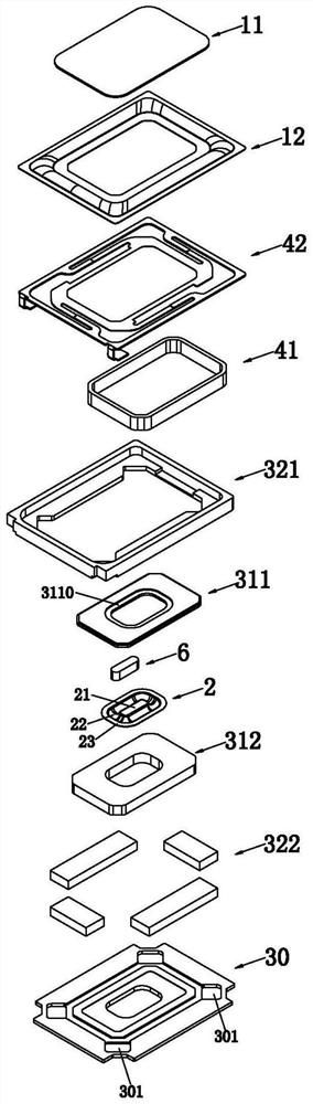
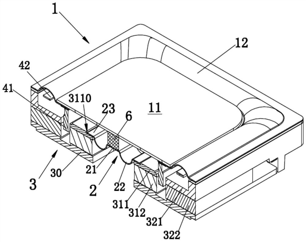
[0033] Such as Figure 1 to Figure 3 As shown, the sound generating device provided by the present invention includes a vibrating assembly and a magnetic circuit assembly 3, wherein the vibrating assembly includes a diaphragm 1 and a voice coil 41 combined with the lower side of the diaphragm 1, wherein "up" and "down" are represented by figure 2 The structure shown prevails. The diaphragm 1 includes a middle part 11 at the middle position and a ring part 12 at the edge, wherein the middle part 11 is a hard material, and the strength of the middle part 11 is greater than that of the ring part 12. During the vibration process, the middle The portion 11 is not deformed. The magnetic circuit assembly 3 is located under the diaphragm 1. The magnetic circuit assembly 3 is a dual magnetic circuit structure including a central magnetic circuit at the center and a side magnetic circuit at the edge. A voice coil is formed between the central magnetic circuit and the side magnetic cir...

Embodiment 2

[0057] Such as Figure 4 As shown, there are three main differences between the present embodiment and the implementation of Lee 1. The connection part 7 is a hollow columnar structure, the flexible deformation part 2 is combined with the lower surface of the upper magnetically conductive plate 311, and the flexible deformation part 2 is connected with the upper magnetic plate 311. A support member 5 is provided between the magnetic conductive plates 311 .

[0058] The connection part 7 of this embodiment is a hollow columnar structure, the upper end surface of the connection part 7 is located on the same plane, and the lower end surface of the connection part 7 is located on the same plane. This structure is beneficial to the connection part 7 and the planar middle part 11 and The planar intermediate portion 21 is fixedly joined. Wherein, the upper end surface of the connecting part 7 is fixedly combined with the middle part 11 of the diaphragm 1, and the lower end surface o...


PUM


Abstract

The invention provides a sound production device which comprises a vibration assembly and a magnetic circuit assembly, the vibration assembly comprises a diaphragm, the middle area of the magnetic circuit assembly is hollowed out to form an expansion cavity penetrating through the magnetic circuit assembly, and the area, located in the expansion cavity, of the magnetic circuit assembly is providedwith a flexible deformation part; the flexible deformation part is arranged opposite to the vibrating diaphragm; the vibrating diaphragm comprises a middle part located at the middle position and a folding ring part located at the edge position; the sound production device further comprises a connecting part, the connecting part is arranged between the vibrating diaphragm and the flexible deformation part, the connecting part is fixedly connected with the middle part and the flexible deformation part, and the vibrating diaphragm and the flexible deformation part vibrate synchronously. According to the sounding device, the equivalent volume of the rear vocal cavity of the sounding device is increased, the low-frequency sensitivity of the sounding device is improved, and the polarization ofthe vibrating diaphragm can be inhibited.

Description

technical field [0001] The present invention relates to the technical field of acoustics, and more specifically, to a sound generating device, an acoustic module and electronic equipment equipped with the sound generating device. Background technique [0002] Generally speaking, the acoustic system of the traditional structure includes a closed box and a sounding unit arranged on the closed box. A cavity is formed between the closed box and the sounding unit. Due to the volume limitation of the cavity in the acoustic system, the acoustic system Especially with small acoustic systems it is difficult to achieve satisfactory bass reproduction. Conventionally, in order to achieve satisfactory bass reproduction in an acoustic system, two methods are usually used. One is to place sound-absorbing materials in the box of the acoustic system to absorb or desorb the gas in the box and play a role in volume. The effect of increasing and then reducing the low-frequency resonance freque...

Claims


Application Information

Patent Timeline
Patent Type & Authority Patents(China)
IPC IPC(8): H04R1/28H04R7/12
CPCH04R1/2811H04R7/12
Inventor 葛连山王兴龙
Owner GEER TECH CO LTD
Why Eureka
Try Eureka