Electro-acoustic converter with novel vibrating system and manufacturing method for vibrating system
An electro-acoustic converter and vibration system technology, which is applied in the direction of fixing/tensioning the diaphragm, sensors, electrical components, etc., can solve the problems of unfavorable production efficiency, difficult assembly of the voice coil tube, and improvement, so as to reduce resonance Effect of frequency and distortion, improved acoustic performance, improved sensitivity
- Summary
- Abstract
- Description
- Claims
- Application Information
AI Technical Summary
Problems solved by technology
Method used
Image
Examples
Embodiment 1
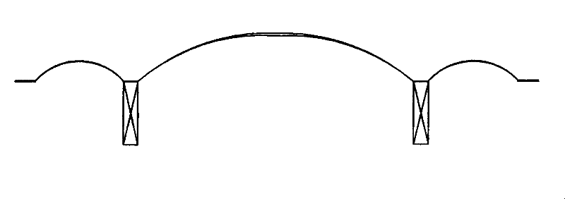
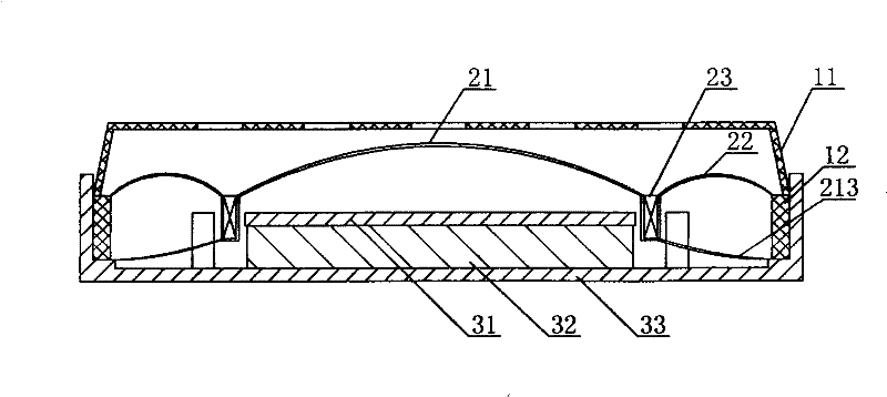
[0032] Such as figure 2 As shown, the miniature dynamic electro-acoustic transducer of the inner magnetic circuit includes an auxiliary system, a vibration system and a magnetic circuit system, and the auxiliary system is fixed in combination with the vibration system and the magnetic circuit system. The auxiliary system includes a front cover 11 and a housing 12; the vibration system includes a diaphragm central part 21, a diaphragm edge part 22 and a voice coil tube 23 combined with the diaphragm central part 21 and the diaphragm edge part 22, and the diaphragm central part 21 and the diaphragm edge portion 22 are independent structures, and the outer edges of the diaphragm center portion 21 and the diaphragm edge portion 22 are circular structures, located on the diaphragm center portion 21 at the lower end of the voice coil tube 23, and away from the diaphragm One side of the central part 21 is integrally provided with a pulling foot 213; the magnetic circuit system inclu...
Embodiment 2
[0039] The difference between the present embodiment and the first embodiment lies in that the number of the pulling feet is different. Such as Figure 10 As shown, the number of pulling feet 213a in this embodiment is three, and the pulling feet 213a are evenly distributed on the edge of the lower end of the supporting part 212a (not shown in the figure) of the voice coil tube 23a corresponding to the central part of the diaphragm 21a , this design can also achieve the above-mentioned technical effects of the implementation process while meeting more actual production needs according to factors such as the magnetic circuit structure. In the improvement of this embodiment, the number of the pulling feet can also be designed as other numbers, and the pulling feet can also be designed in other positions (such as the corners of the square diaphragm) that can balance the vibration system. The preferred embodiment of the present invention In the embodiment, there are at least two ...
Embodiment 3
[0041] Such as Figure 11 As shown, the difference between this implementation process and the above-mentioned implementation is that the edge shape of the diaphragm central portion 21b is different from the outer edge shape of the diaphragm edge portion 22b. In this solution, the outer edge shape of the central part of the diaphragm central part 21b is circular, and the hollow structure of the diaphragm edge part 22b is a circle corresponding to the diaphragm central part 21b, but the outer edge shape is designed as a racetrack. In the improvement of this implementation process, the hollow part of the central portion 21b of the diaphragm and the edge portion 22b of the diaphragm can also be designed to correspond to different combinations of known structures of the diaphragm such as circular, track-shaped, elliptical, and other diaphragm structures.
PUM
 Abstract
Description
Claims
Application Information
 - R&D
- Intellectual Property
- Life Sciences
- Materials
- Tech Scout
- Unparalleled Data Quality
- Higher Quality Content
- 60% Fewer Hallucinations
Browse by: Latest US Patents, China's latest patents, Technical Efficacy Thesaurus, Application Domain, Technology Topic, Popular Technical Reports.
© 2025 PatSnap. All rights reserved.Legal|Privacy policy|Modern Slavery Act Transparency Statement|Sitemap|About US| Contact US: help@patsnap.com


