Method of injection molding thin thermoplastic lenses

Active Publication Date: 2006-12-14
ESSILOR INT CIE GEN DOPTIQUE
View PDF56 Cites 3 Cited by
  • Summary
  • Abstract
  • Description
  • Claims
  • Application Information

AI Technical Summary

Benefits of technology

[0013] It is a further object of the present invention to utilize a clamp-end coining process to provide strong, high-yield lenses.
[0015] The flow resistance is reduced by venting the cavity through the open parting line of the mold or reducing the flow resistance, or a combination of both. During the injecting step, the molding material is in intimate contact with the inserts at a thickness greater than the final coined lens thickness. The coining step reduces the thickness of the lens to between 0.5 and 0.6 mm thick as the mold closes. Following the injecting step, the method further includes the step of shifting the injector to packing pressure mode so that molding material stops flowing into the cavity. For clamp-end coining, the inserts are secured in a fixed position within their respective sleeves, so that force exerted on the inserts by the molding material is transferred to the mold clamp.

Problems solved by technology
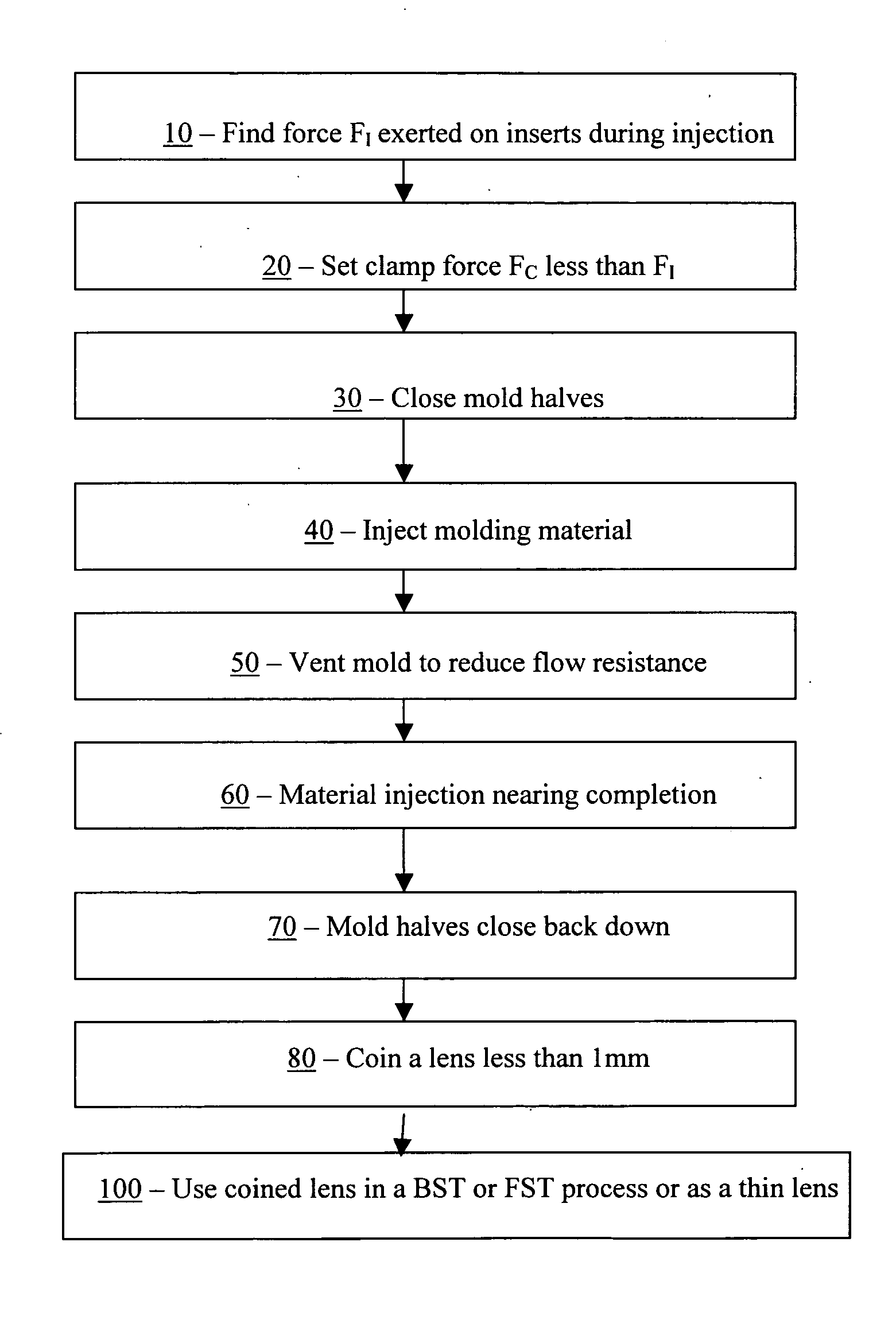
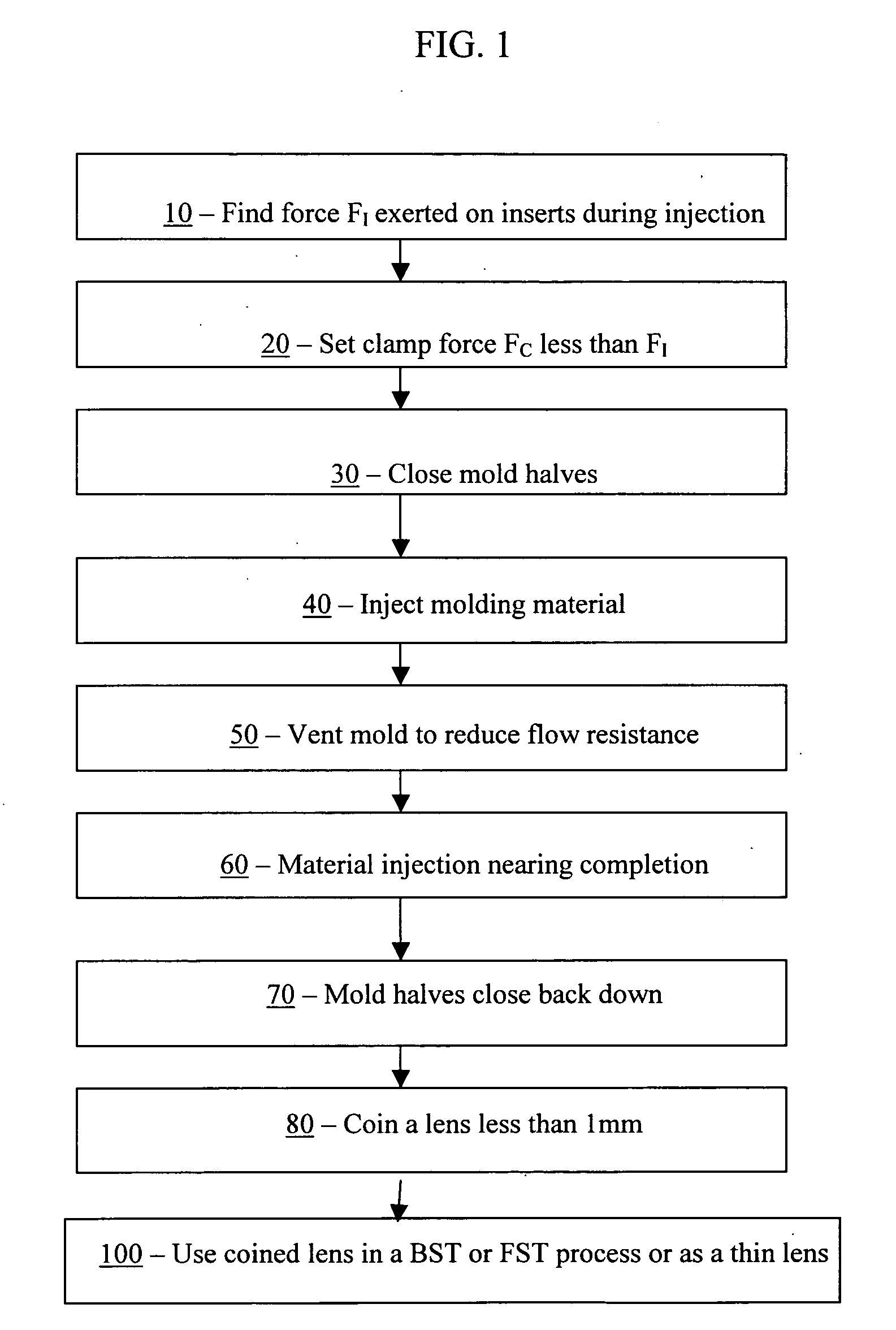
The paths from the gate to the edge points of the mold cavity are not symmetrical and therefore make it difficult to control the thermodynamics of the cooling melt flow.
As lens cavities become thinner, straight injection molding techniques are unable to fill the mold without premature freeze-off.
Among the problems noted is the inability to mold thin centered lenses under the high clamp pressure and tendency for such systems to create flash and damage the equipment.
These systems typically exert a compressive force less than the clamp force, frequently in applications where it is believed that clamp force is excessive.
However, they add cost and complexity to molding systems.

Method used


Image

  • Method of injection molding thin thermoplastic lenses
  • Method of injection molding thin thermoplastic lenses

Examples


example 1

[0029] A Cincinnati RoboShot was configured to operate at maximum injection speed of 5.9 inches per second (ips), maximum injection pressure of 24,000 psi and maximum clamp tonnage of 110 U.S. tons. The machine was equipped with a 2-cavity, 71mm diameter mold from APEX. One cavity was blocked, and the other held a 6-base stock plano steel insert set. Thin carriers were molded with Bayer DP1-1265 and Bayer 2407 under the following process parameters:

Mold Temperature:280 degrees F.Melt Temperature:595 degrees F.Injection Speed:5.9 ips - one stepPacking:12,000 psi - 2 sec; 10,000 psi - 3 sec;5,000 - 5 sec

The Bayer DP1-1265 resin produced the thinnest lenses having a center thickness slightly above 0.6 mm. Lenses with a 0.65 mm center thickness were common, thereby failing to achieve the objective of molding lenses about 0.5 mm. Since the carriers were thicker than desired, it followed that the BST yield ranged from 44% to 78%. Other problems included non-uniform thickness, base curv...

example 2

[0035] A further test was conducted with an Engel conventional high speed machine operating at the maximum 200 ton hydraulic clamp force and the maximum injection speed of 40 ips. The 2-cavity, 76mm diameter mold was used. Both GE OQ1030 (CD grade) and GE HF1110 (high flow) resins were used. The OQ1030 achieved an actual injection speed of 25 ips and carriers having a center thickness of 0.5 mm were obtained. For the HFI110,carriers with center thicknesses slightly under 0.6 were obtained. BST laminating tests of the resulting carriers in applying PHC (protected hard coat) resulted in a 90% yield.

[0036] The parts from the Engel machine were characterized by the presence of excess flash. During injection, it was observed that the parting line was forced open allowing the resin to flow out of the boundary of the mold inserts. At the same time, however, resin was easily able to flow across the inserts as the passage was wider and pressure from within the cavity was released. According...

example 3

[0037] A Nissei FN4000 having a 200 ton hydraulic clamp was configured to operate at 75% of maximum clamp force to obtain a better balance with the maximum injection speed of 132 mm / sec [5.2 ips]. Bayer DP1-1265 and GE OQ1030 were utilized in the example with a melt temperature of 595 degrees F and a mold temperature of 265 degrees F. The process was utilized to mold a pair of 76mm 6-base plano steel insert in a 60 second cycle. Due to excess flash, secondary processing including degating and die-cutting was needed to obtain the final carriers. However, the quality of the resulting carriers is almost on par with regular plano lenses, and is superior to those obtained from surfacing. Lens having a center thickness of about 0.56 mm were produced consistently. In a subsequent test of the carriers with full HMC stack, resulted in an 86% acceptable yield. The carriers resulting from this example are compared to surfaced carriers and thermoformed carriers in the following Table 3.

TABLE ...


PUM


Abstract

Methods are disclosed to injection mold resins, like polycarbonate, to form solid optical lenses. The lenses are ideally suited for use as very thin coating carriers. The method involves closing the mold with a clamp force less than the force exerted on the insert during injection. During injection the mold is allowed to breathe thereby overcoming many of the obstacles associated with injection molding very thin lenses. As the injection pressure subsides, the mold begins to close to perform a coining operation, resulting in a strong, high yield carrier or lens.

Description

BACKGROUND OF THE INVENTION [0001] 1. Field of the Invention [0002] The present invention relates to a method injection molding ultra thin thermoplastic lenses. The lenses produced according to the invention have particular utility as carriers in the Transfer process as described in the patent application WO 03 / 004255. [0003] 2. Description of the Related Art [0004] Lenses and other articles manufactured at optical quality, have exacting demands for mold replication, high optical transmission and impact resistance. In the 2002 Polycarbonates publication, Brunelle and Kailasam describe how polycarbonate is prepared by the transesterification of a bisphenol-A with a carbonate. U.S. Pat. No. 5,212,280 describes diphenols which are useful in the condensation method of producing polycarbonate in the presence of phosgene. [0005] Injection molding of lenses requires edge gating so that the runner ends up remote from the lens surfaces. The paths from the gate to the edge points of the mold ...

Claims


Application Information

Patent Timeline
IPC IPC(8): B29D11/00
CPCB29D11/0073B29D11/00009
Inventor CHIU, HAO WENMAYR, ROGER A.YANG, HSINJIN E.
Owner ESSILOR INT CIE GEN DOPTIQUE
Why Eureka
Try Eureka