
Fluxing compositions

a composition and composition technology, applied in the direction of soldering apparatus, semiconductor/solid-state device details, manufacturing tools, etc., can solve the problems of failure of semiconductor packages, corrosion of semiconductor packages, and inconvenient chemistries of anhydride-based fluxing agents

Inactive Publication Date: 2006-12-07
NAT STARCH & CHEM INVESTMENT HLDG CORP
View PDF14 Cites 25 Cited by
  • Summary
  • Abstract
  • Description
  • Claims
  • Application Information

AI Technical Summary

Benefits of technology

[0010] This invention is a fluxing composition comprising a fluxing agent, in which the fluxing agent is a compound having (i) an aromatic ring, (ii) at least one —OH, —NHR (where R is hydrogen or lower alkyl), or —SH group, (iii) an electron-withdrawing or electron-donating substituent on the aromatic ring, and (iv) no imino group. For purposes of this specification and the claims, aromatic is deemed to include five- and six-membered ring structures, including heterocyclic ones, that have delocalized 4n+2 pi electrons. The aromatic ring may be fused with one or more aliphatic or other aromatic ring structures. The —OH, —NH, or —SH group protons on the fluxing agent have pKa values roughly in the range of 5 to 14, and yet are capable of acting as fluxes for metals or metallic materials.

Problems solved by technology

The coefficients of thermal expansion (CTE) of the semiconductor die, solder, and substrate are dissimilar and this mismatch stresses the solder joints, which ultimately can lead to failure of the semiconductor package.
The carboxylic acids from the anhydrides are volatile during the thermal compression bonding process, and may cause corrosion of the semiconductor packages.
Moreover, anhydride based fluxing agents are not suitable for chemistries that are sensitive to acidic species, such as, cyanate ester based underfill resins.
The more reactive anhydrides are too aggressive, causing the resin monomers and oligomers to advance, leading to short resin pot life and voiding during curing.
The voiding can negatively impact the interconnections between the solder balls and substrates, causing short circuits and joint failure.

Method used


Image

  • Fluxing compositions
  • Fluxing compositions
  • Fluxing compositions

Examples


example 1

[0032] In this example, various compounds were tested for performance as fluxes applied directly to solder, as would be done prior to a capillary flow operation. Performance was measured as the time in seconds it took for the fluxing agent to collapse a solder ball. Copper or gold-plated copper coupons were used as substrates and the solder was a lead-free Sn95.5Cu3.8Ag0.7 solder having a melting point of 217° C. (The melting point of the solder will vary depending on the actual metallurgy.) The substrate coupons were preheated on a hot plate to 240° C. (a temperature higher than the melting point of the solder), five to ten mg of fluxing agent were dropped onto the heated hot plate, and then four to six granules of solder, enough to make a solder ball, were dropped onto the fluxing agent. When a solder ball starts to flux, it rapidly collapses and merges into a solder glob that displays a shiny surface. This reaction was observed on all the examples tested and the time elapsed befo...

example 2

No-Flow Fluxing Compositions

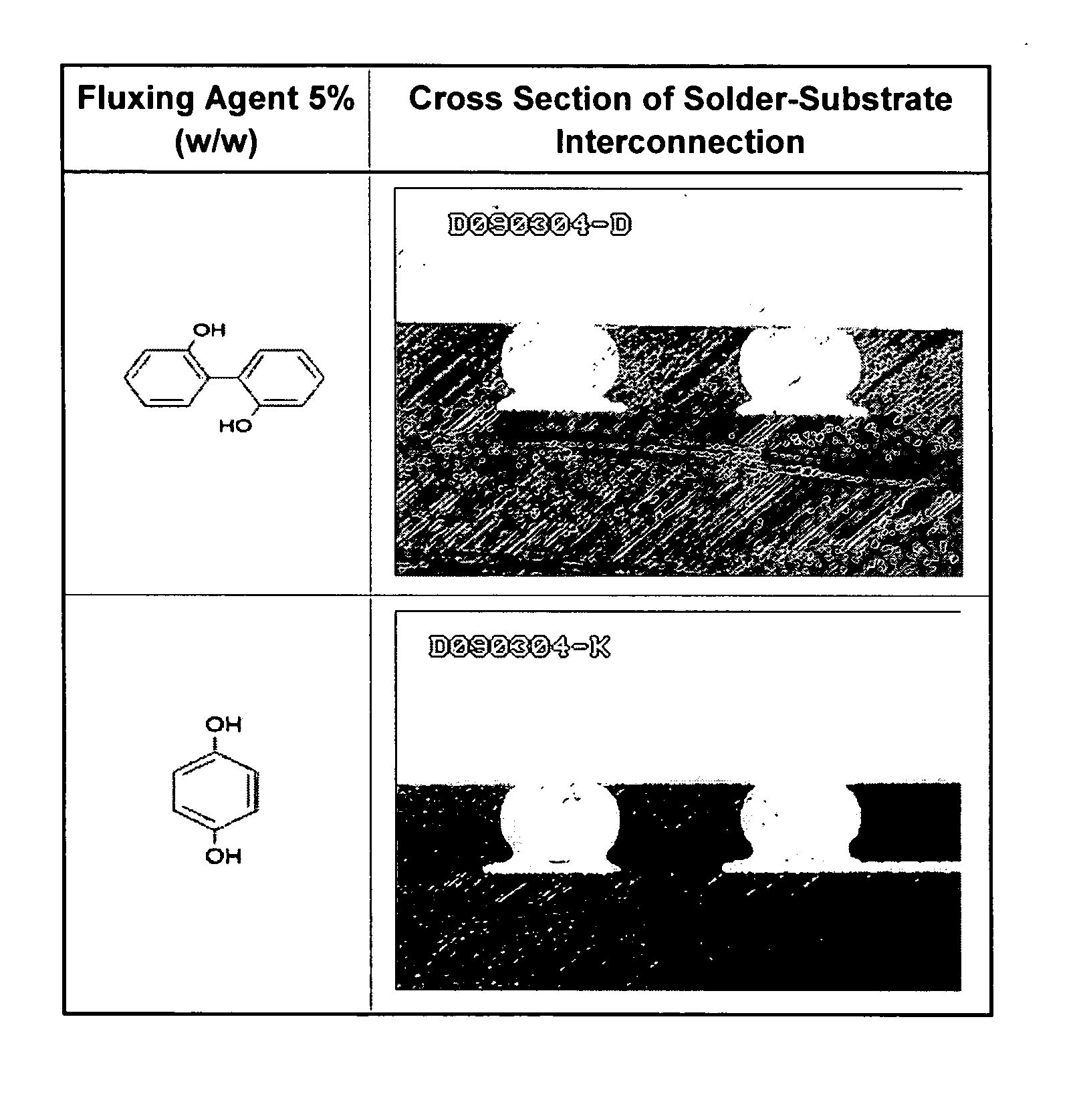
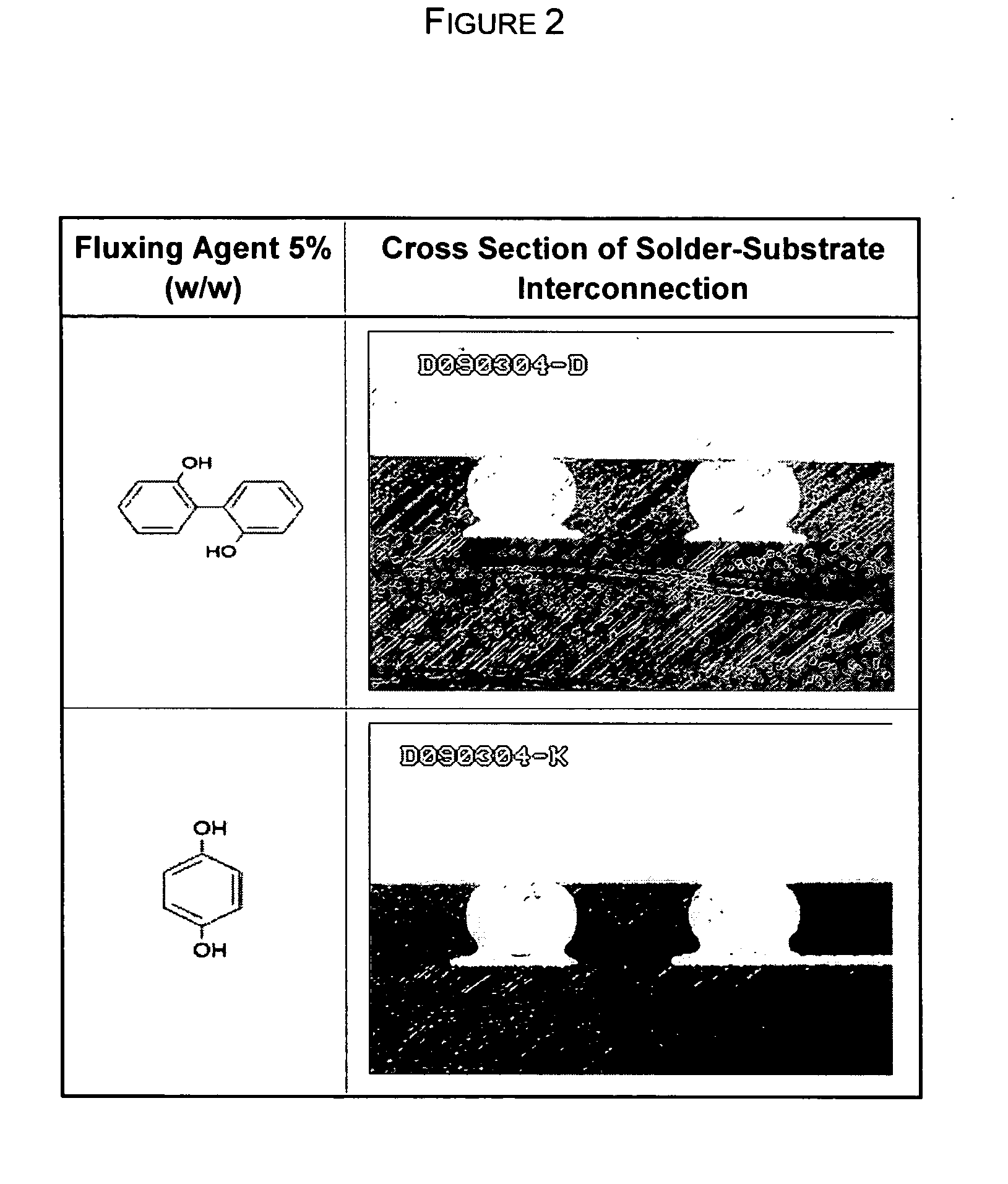
[0033] In this Example, fluxing agents were tested in no-flow fluxing underfill compositions. Assemblies of a solder bumped die and substrate were prepared using a thermal compression Toray Bonder to establish electrical interconnections between the bumped die and the substrates. The fluxing compositions were dispensed onto a BT substrate covered by solder mask with the exposed traces being Ni / Au plated onto Cu. A silicon die (5×5 mm) bumped with Sn95.5Cu3.8Ag0.7 solder bumps was aligned with the exposed traces on the substrate. The substrate was heated to 80° C. and the die and substrate contacted with pressure of 20 Newtons in the thermal compression bonder. The die was then heated in ramped profile from 200° C. to 220° C. within 1-2 seconds and held at 220° C. for 5-6 seconds to form an assembly of silicon die and substrate. The electric connections of the solder joints were confirmed by measuring the resistance across the circuits using an Agilent 34...

example 3

Capillary Flow Underfill. Eutectic Solder.

[0046] Two BT substrates covered by solder mask with the exposed traces being Ni / Au plated onto Cu and two 10×10 mm silicon dies bumped with eutectic solder Pb63Sn37, were brushed with fluxing agents prior to solder reflow and capillary flow underfill operations as described in the Background section of this specification. One set of parts was brushed with a commercial fluxing agent sold by Kester as product number 6502. The other set was brushed with a fluxing agent comprising a solution of 3-hydroxy-2-methyl-4-pyrone

tripropylene glycol (3% w / w). The parts were dried in air and the die bonded to the substrate using a GSM Flipchip die bonder. The electric connections of the solder joints were confirmed by measuring the resistance across the circuits using an Agilent 34401 Digit Multimeter. The capillary flow underfill, which was a proprietary composition comprising a cyanate ester resin, was dispensed along the edge of the die and allowe...


PUM


Abstract

A fluxing composition comprises a fluxing agent in which the fluxing agent is a compound having (i) an aromatic ring, (ii) at least one —OH, —NHR (where R is hydrogen or lower alkyl), or —SH group (iii) an electron-withdrawing or electron-donating substituent on the aromatic ring, and (iv) no imino group.

Description

FIELD OF THE INVENTION [0001] This invention relates to fluxing compositions and their application in electronic packaging, particularly within no-flow underfill compositions and pre-applied wafer level underfill for flip-chip based semiconductor packages and electronic assemblies. These compositions also have application for refluxing the solder during solder reflow prior to a capillary underfill process. BACKGROUND OF THE INVENTION [0002] An increasingly important method for attaching an integrated circuit onto a substrate in semiconductor packaging operations is the so-called flip-chip technology. In flip-chip technology, the active side of the semiconductor die is bumped with metallic solder balls and flipped so that the solder balls can be aligned and placed in contact with corresponding electrical terminals on the substrate. Electrical connection is realized when the solder is reflowed to form metallurgical joints with the substrates. The coefficients of thermal expansion (CTE...

Claims


Application Information

Patent Timeline
Patent Type & Authority Applications(United States)
IPC IPC(8): B23K35/34
CPCB23K35/36B23K35/3612H01L2924/10253B23K35/3613B23K35/362H01L21/563H01L23/293H01L2224/73203H01L2924/0102H01L2924/01025H01L2924/01079H01L2924/12044H05K3/3489H01L2924/01322H01L2224/73204H01L2924/00H05K3/34
Inventor WANG, RENYILIU, ZHENBAO, LIRONGTRAN, TRANGMUSA, OSAMA M.
Owner NAT STARCH & CHEM INVESTMENT HLDG CORP
Learn More