
Ceramic foam filter for better filtration of molten iron

a ceramic foam filter and ceramic foam technology, applied in the field of ceramic foam filter, can solve the problems of difficult slag retention in strainer-type filters, unavailable mullite foam filters for foundry applications, etc., and achieve the effect of cleaning and more machineable iron castings

Active Publication Date: 2006-11-30
PORVAIR
View PDF14 Cites 14 Cited by
  • Summary
  • Abstract
  • Description
  • Claims
  • Application Information

AI Technical Summary

Benefits of technology

[0008] It is an object of the present invention to provide a mullite foam wherein the wetting characteristics in iron is utilized within the tortuous path of the foam to produce a filter which is superior to either silica-bonded SiC foam or mullite strainers, creating cleaner, more machineable iron castings.
[0009] It is another object of the present invention to provide an improved method for filtering iron.
[0010] It is another object of the present invention to provide a filter with improved wettability to FeO, improved thermal shock resistance and a tortuous flow path.

Problems solved by technology

Mullite filters may better retain liquid slag during filtration but mullite foam filters for foundry applications have been unavailable.
Slag retention is difficult in strainer-type filters.
Substituting SiC with mullite has proven to be elusive and proper design of the binder for formulation of a filter with the appropriate mechanical properties at both room and high temperature has not been previously discovered.

Method used


Image

  • Ceramic foam filter for better filtration of molten iron
  • Ceramic foam filter for better filtration of molten iron
  • Ceramic foam filter for better filtration of molten iron

Examples


example 1

[0041] A ceramic precursor composition was prepared utilizing the materials listed in Table 1. In Table 1, the refractory aluminosilicate used was Mulcoa 60®, ground to a −325 mesh, as available from C-E Minerals. Colloidal silica was used as obtained from Nyacol. Modified bentonite was used as obtained from Wyo-Ben, Inc. Fumed silica was used as obtained from CE Minerals. The composition was fired at 1200° C. for 30 min. Fused silica could substitute for fumed silica to improve the ability to cut the ceramic foam in the fired state. The modulus of rupture was measured at ambient temperature as reported in Table 2. The modulus of rupture was measured at a high temperature as reported in Table 3.

TABLE 1ComponentWt %refractory aluminosilicate54.50colloidal silica21.00modified bentonite0.75Fumed silica17.75water6.00

[0042] The average room temperature modulus of rupture (MOR) of the filter is approximately 90-psi over the given density range. This value is acceptable for most molten m...

example 2

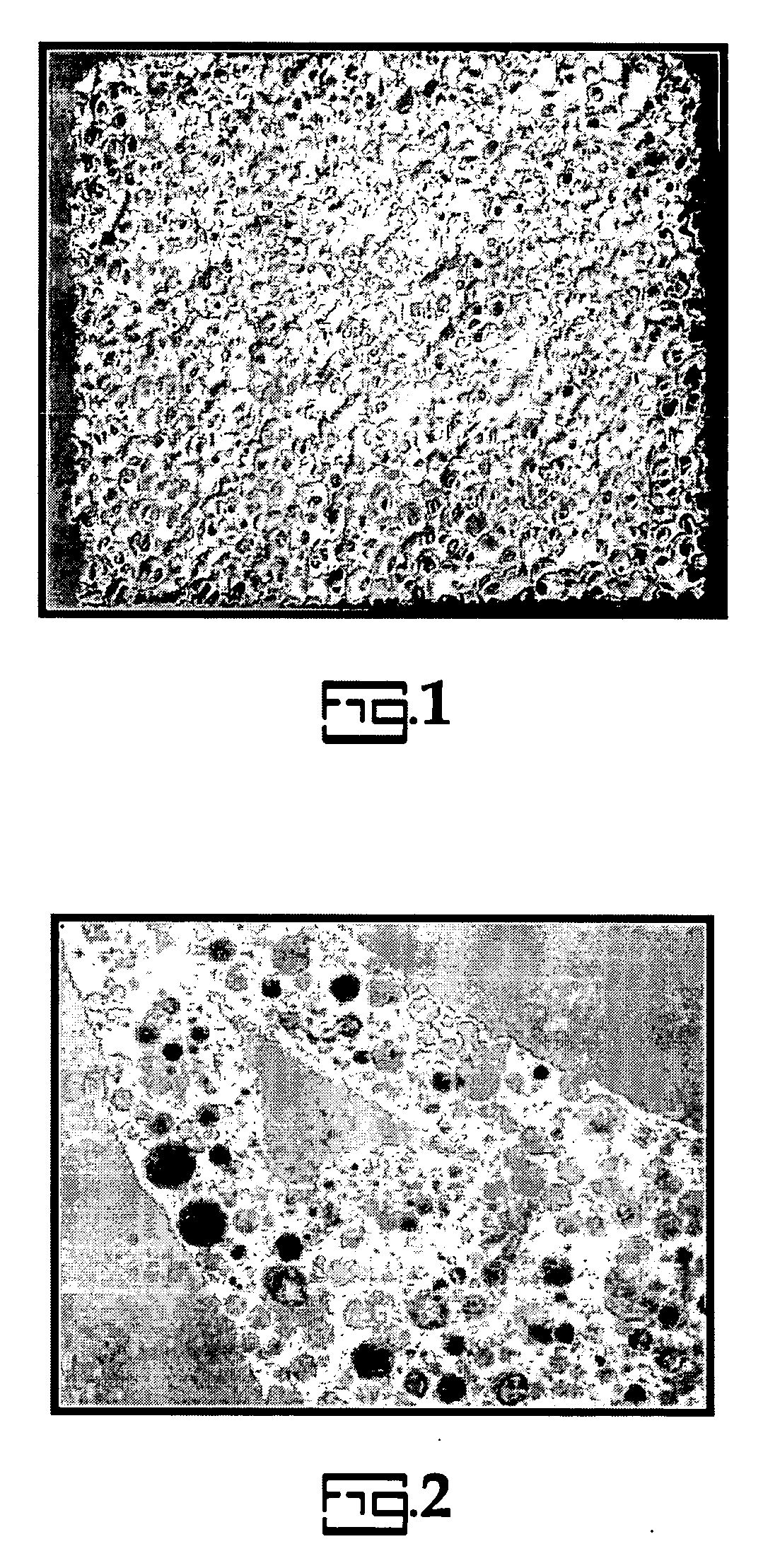
[0044] To improve liquid slag retention and capacity a composition was prepared as in Table 1 with the further inclusion of 4 wt % hollow organic spheres with a diameter of 80 μm. The resulting filter was examined under an electron microscope and the resulting microstructure is shown in FIG. 2. When the liquid slag wets the mullite body, it can be drawn into the micropores via capillary action.

example 3

[0045] A filter was prepared under the same conditions as Example 1 with the composition provided in Table 4. Mulcoa 70® was used as the refractory aluminosilicate as available from C-E Minerals.

TABLE 4ComponentWt %Refractory aluminosilicate54.5colloidal silica21.0modified bentonite0.8silica fume17.8water5.9

[0046] The resulting average hot MOR was measured to be 34 psi at an average foam relative density of 14%.


PUM

PropertyMeasurementUnit
Fractionaaaaaaaaaa
Fractionaaaaaaaaaa
Pressureaaaaaaaaaa

Abstract

A ceramic precursor, and ceramic filter prepared therewith, with 35-70 wt % refractory aluminosilicate; 10-30 wt % colloidal silica; 0-2 wt % modified bentonite; 0-35 wt % fumed silica; 0-10 wt % pore formers and liquid.

Description

CROSS-REFERENCE TO RELATED APPLICATIONS [0001] The present application claims priority to U.S. Provisional Application No. 60 / 706,577 filed Aug. 9, 2005 which is pending and incorporated herein by reference. The present application is a continuation-in-part of pending U.S. patent application Ser. No. 11 / 389,841 filed Mar. 27, 2006 which claims priority to expired U.S. Provisional Application No. 60 / 665,760, filed Mar. 28, 2005 both of which are incorporated herein by reference.BACKGROUND [0002] The present invention is related to an improved ceramic foam filter. More particularly, the present invention is related to a ceramic foam filter for molten iron with sufficient mechanical properties for use in capturing and retaining high FeO liquid slags, other metal oxide slags, and other entrained particulates. [0003] A significant portion of iron foundries use pressed or extruded mullite strainers. A ceramic foam filter is expected to perform better than a strainer due to its tortuous fl...

Claims


Application Information

Patent Timeline
IPC IPC(8): C02F1/00
CPCB01D39/2093C04B35/185C04B38/0655C04B2111/00793C04B2111/00887C04B38/0054C04B38/067
Inventor OLSON, RUDOLPH A. IIIAUBREY, LEONARD S.CHI, FENGPLANTEC, CHRISTOPHER J.REDDEN, MYRON K.HAACK, DAVID P.
Owner PORVAIR
Learn More