
Humid air turbine cycle with carbon dioxide recovery

a carbon dioxide recovery and humid air technology, applied in steam engine plants, machines/engines, mechanical equipment, etc., can solve the problems of low carbon dioxide removal efficiency, limited use of all or almost all physical solvents, and high energy consumption of methods, so as to improve the efficiency of carbon dioxide removal

Inactive Publication Date: 2006-11-23
FLUOR TECH CORP
View PDF8 Cites 51 Cited by
  • Summary
  • Abstract
  • Description
  • Claims
  • Application Information

AI Technical Summary

Benefits of technology

[0007] The present invention is directed to methods and configurations of carbon dioxide removal from flue gases in which at least part of the flue gas is compressed to a higher pressure thereby improving carbon dioxide removal efficiency.

Problems solved by technology

However, and especially depending on the feed gas composition, membrane life time is less than desirable, or the feed gas requires pretreatment before contacting the membrane.
Furthermore, membrane systems typically operate at a relatively high pressure differential, which either necessitates a blower or other pressure increasing equipment for low pressure feed gases or disqualifies membrane systems for such low pressure feed gases.
Thus, all, or almost all physical solvents exhibit only limited usefulness for the removal of carbon dioxide from flue gases which are typically near atmospheric pressure, and especially where the flue gas has a relatively low carbon dioxide content.
However, such methods are often energy intensive as well as costly and problems with corrosion and solvent degradation frequently arise (see e.g., U.S. Pat. No. 2,065,112, U.S. Pat. No. 2,399,142, U.S. Pat. No. 2,377,966, U.S. Pat. No. 4,477,419, or U.S. Pat. No. 3,137,654).
Thus, although various carbon dioxide removal configurations and processes are known in the art, all or almost all of them suffer from one or more disadvantages, especially where the partial pressure and / or concentration of the carbon dioxide in the feed gas is relatively low.

Method used


Image

  • Humid air turbine cycle with carbon dioxide recovery
  • Humid air turbine cycle with carbon dioxide recovery
  • Humid air turbine cycle with carbon dioxide recovery

Examples


Embodiment Construction

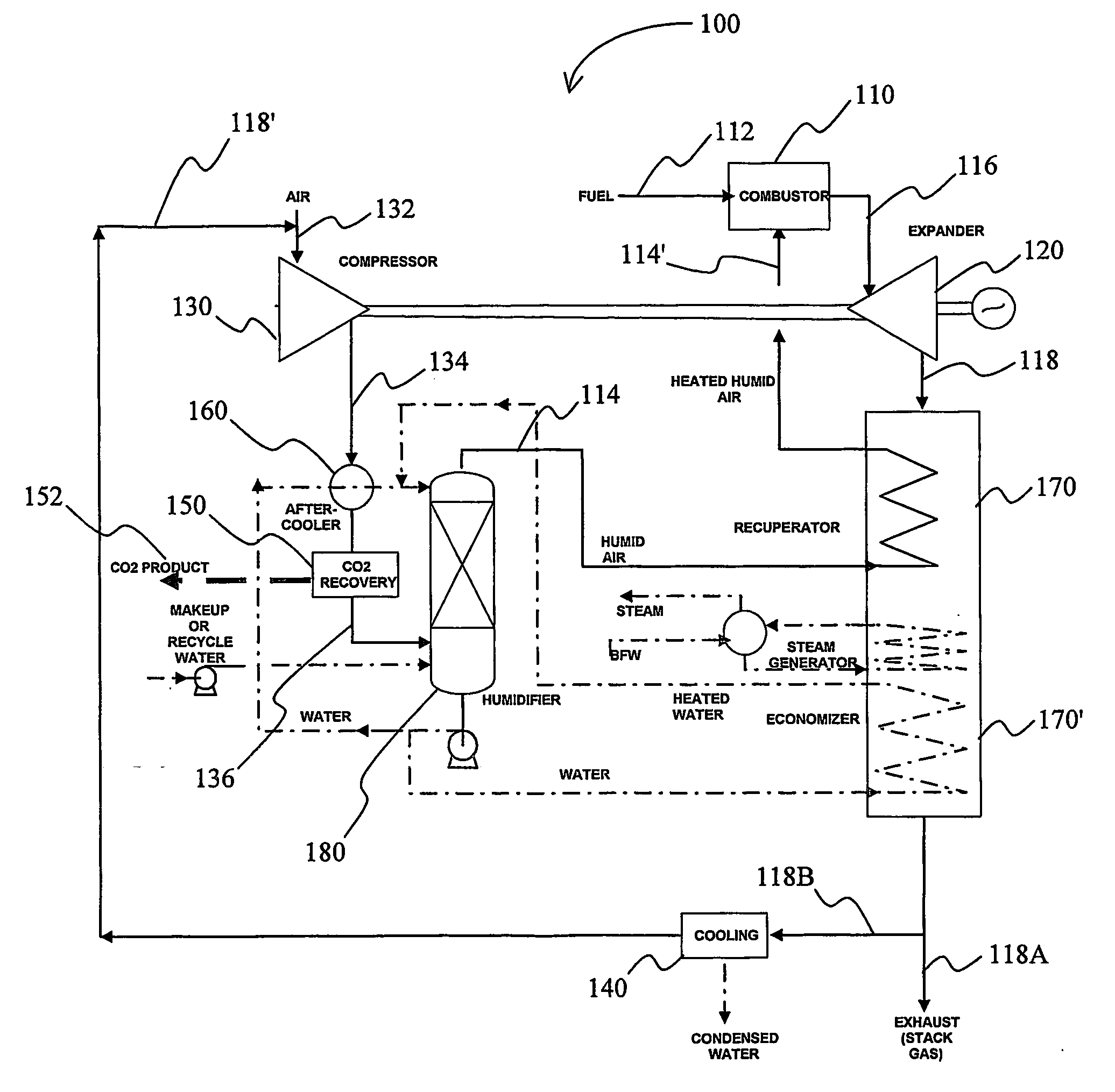
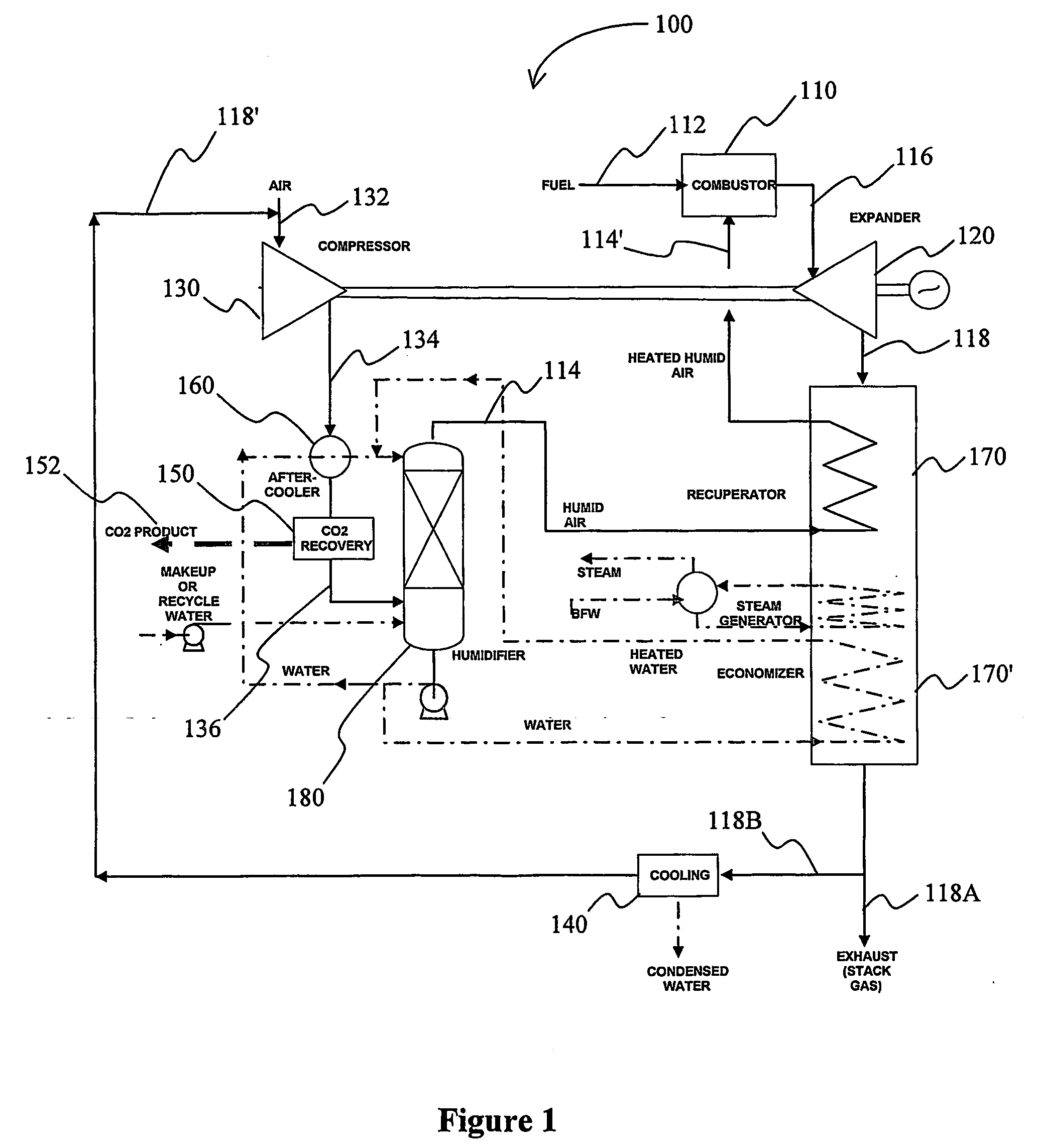
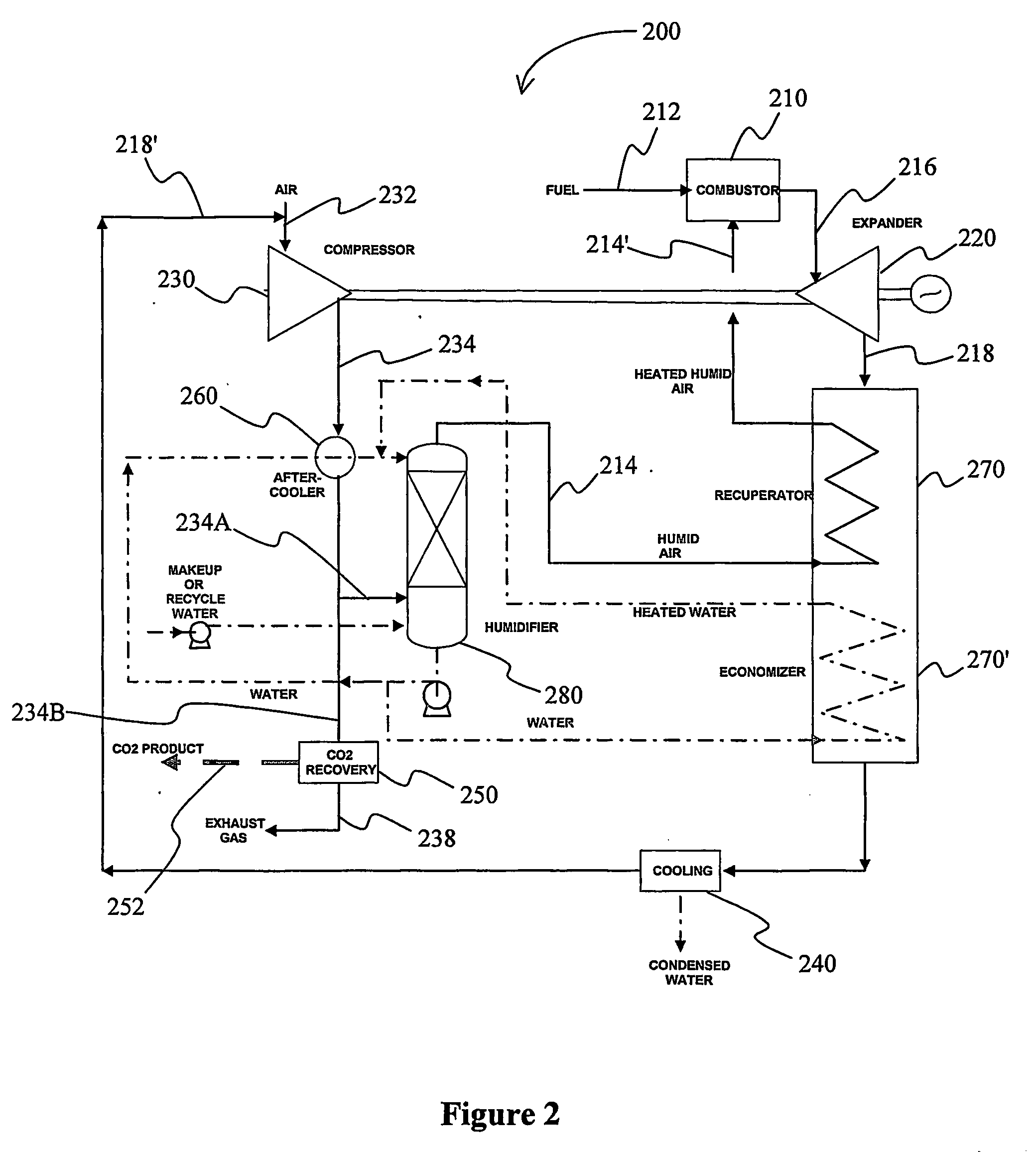
[0016] The inventor has discovered that carbon dioxide contained in the exhaust gas of a gas turbine can be recovered at pressure by recycling at least part of the exhaust gas back to a compressor to increase the partial pressure of the carbon dioxide in the compressed gas, and to thereby facilitate removal of the carbon dioxide using appropriate acid gas removal technologies (e.g., using a physical or chemical solvent, a carbon dioxide specific membrane, or an autorefrigeration process).

[0017] In one particularly preferred configuration as depicted in FIG. 1, an exemplary plant 100 includes a humid air turbine cycle for generation of power, wherein at least part of the expanded exhaust is recycled back to the compressor for carbon dioxide recovery at elevated pressure. More specifically, the combustor 110 receives fuel 112 and heated humid air 114′ and produces exhaust 116 which is subsequently expanded in expander 120. The heat in expanded exhaust 118 is then at least partially r...


PUM


Abstract

Carbon dioxide (152) is removed following compressor (130) which compresses a mixture of compressed air (132) and recirculated exhaust gas (118′) from a gas turbine (120). The carbon dioxide depleted gas (136) is humidified (180, 114) and fed to the combustor (110).

Description

FIELD OF THE INVENTION [0001] The field of the invention is carbon dioxide recovery, and especially carbon dioxide recovery from humid air turbine cycle. BACKGROUND OF THE INVENTION [0002] Combustion gases, and especially flue gases from gas turbines often comprise a substantial quantity of carbon dioxide, which is a known greenhouse gas. Thus, isolation and / or sequestration of carbon dioxide from combustion processes has gained significant attention over the last decade, and there are numerous configurations and methods known in the art to remove carbon dioxide from a flue gas. [0003] For example, carbon dioxide may be removed from various gas streams with one or more membranes as described in U.S. Pat. No. 4,130,403 to Cooley et. al., U.S. Pat. No. 4,639,257 to Duclcett et. al., or U.S. Pat. No. 5,233,837 to Callahan. Membrane processes typically exhibit relatively high selectivity towards a particular gas component. Moreover, membrane processes can generally be operated without e...

Claims


Application Information

Patent Timeline
IPC IPC(8): F02C3/30
CPCF01K11/02F01K13/00F01K21/047F05D2270/08F02C3/30F02C6/18F02C7/08F02C1/08
Inventor RAO, ASHOK
Owner FLUOR TECH CORP
Learn More