
Enhanced reliability sealing system

a sealing system and reliability technology, applied in the direction of engine seals, mechanical equipment, engine components, etc., can solve the problems of reducing the inherent lubrication properties of the medium, ignoring the type of sealing, and ignoring the problem of self-care, so as to achieve the effect of redundancy in the operation of the sealing system

Inactive Publication Date: 2006-11-09
DULIN ROBERT D
View PDF15 Cites 48 Cited by
  • Summary
  • Abstract
  • Description
  • Claims
  • Application Information

AI Technical Summary

Benefits of technology

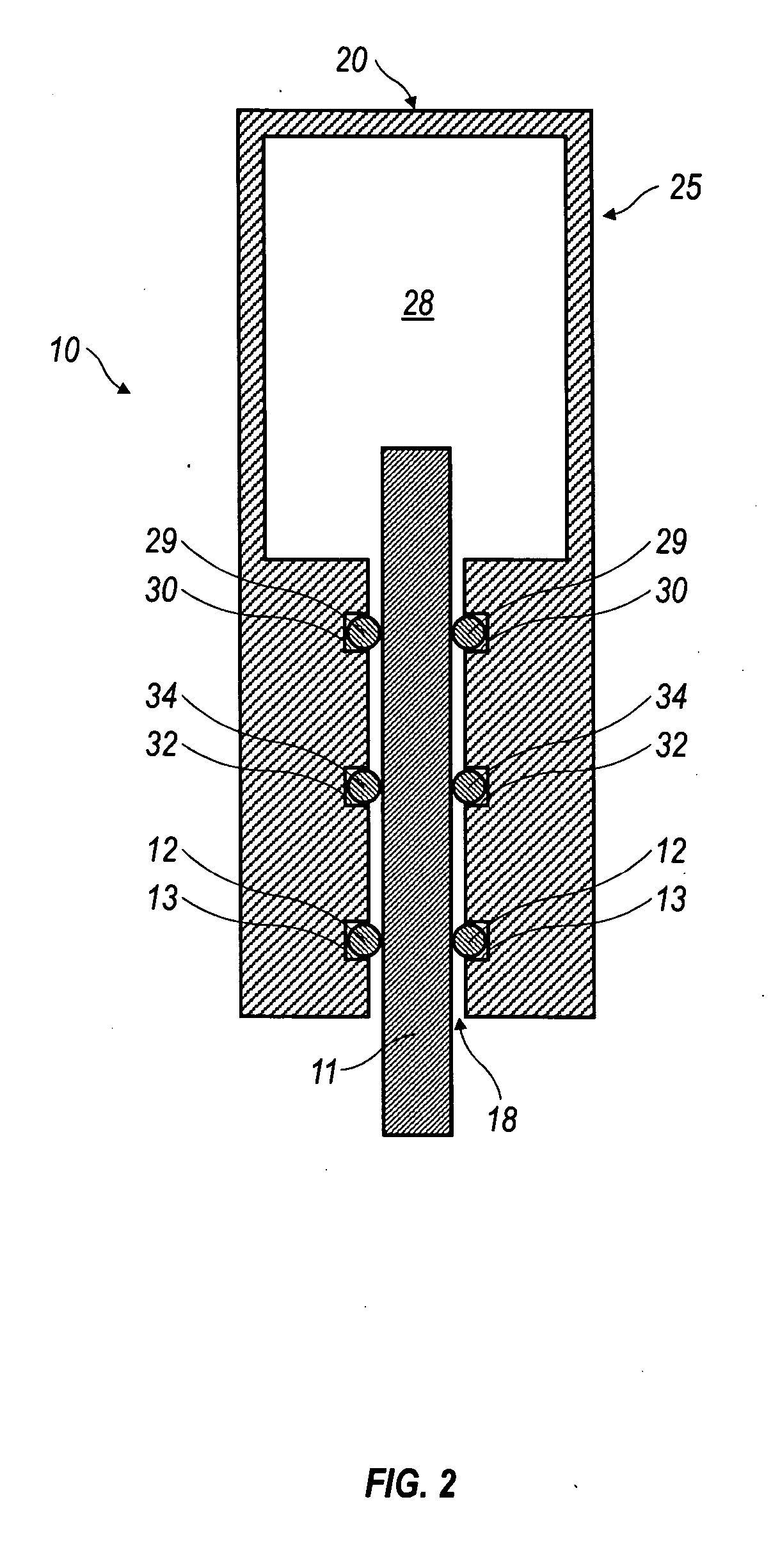
[0016] In another embodiment the present invention is directed towards an enhanced reliability sealing system for sealing a processing medium having two or more sealing elements disposed axially along a movable rod, and a lubricating agent entrapped between each pair of sealing elements capable of providing lubrication between the seals and the movable rod. The lubricating agent is able to dilute at least small quantities of the processing medium being sealed that seep past one of the sealing elements into the lubricant thereby effecting a depression of the sealed medium's freezing point thus enabling the sealing system to operate without damage, at or below the freezing point of the sealed medium. In one aspect the two or more sealing elements and the lubricant are stationary in relation to the wall of a pressure vessel that is being sealed, and wherein the sealing is effected against the movable rod. In another aspect the two or more sealing elements and lubricant are stationary in relation to the movable rod, and wherein the sealing is effected against a wall of a pressure vessel that is being sealed. In even a further aspect more than one type of lubricating agent can be entrapped between pairs of the two or more sealing elements. In a further aspect the volume of lubricant contained between any pair of sealing elements is increased by distance or bore between the two or more sealing elements, thereby enhancing dilution capacity of the lubricant. The lubricating agent selected can further be capable of neutralizing adhesive, corrosive, polymerizing, freezing or seal degrading properties of the processing medium being sealed. In one embodiment the distance between a proximate and distal sealing element is greater than the slidable movement of the rod or shaft, thereby enclosing and protecting the sealing surface from exposure to either the environment or the process medium and their possible corrosive or otherwise degrading effects.
[0017] The present invention is also directed towards a method of sealing process fluid from the environment. This method includes disposing two or more sealing elements axially along a movable rod, and entrapping a lubricant between pairs of the two or more sealing elements. The lubricant is preferably able to neutralizing adhesive, corrosive, polymerizing, freezing or seal degrading properties inherent to the process fluid. Further, the seal is more reliable due to the redundancy of the multiple sealing elements, and is also more resistant to failure from damage caused by properties of the process fluid sealed or failure and subsequent leakage of any one seal.

Problems solved by technology

However, there are several problems that these types of seals fail to address.
For example, these types of seals must be lubricated or wear and frictional heat will damage them.
If the pressure vessel contains a liquid or gas medium that is sealed and has lubricating properties, the problem takes care of itself, except when the temperature of the fluid or gas being sealed falls below its individual freezing point.
In such instances, the subsequent freezing and solidification can diminish the medium's inherent lubrication properties.
When pressurized fluid or gas must be contained within the pressure vessel with minimal leakage, these common seals do not function well as fluids and gases have variable tendencies to leak past any given seal according to their individual seal ability.
Should the temperature of the sealed medium pass through one of its phase change transition temperature (e.g., gas to liquid or liquid to solid), the change, especially from liquid to solid, can have unwanted effects upon the seal system.
Difficulties can also occur when centering or aligning the rod that passes through the centerline of the bore of the seal, such as causing a side load.
An externally induced side load can abrade or prematurely wear the sealing element, resulting in leaks in the sealing system.
Other problems include corrosion such as pitting of the rod, or adherence of foreign substances to the polished seal surface of the rod that slides against the resilient seal.

Method used


Image

  • Enhanced reliability sealing system
  • Enhanced reliability sealing system
  • Enhanced reliability sealing system

Examples


Embodiment Construction

[0022] As required, detailed embodiments of the present invention are disclosed herein. However, it is to be understood that the disclosed embodiments are merely exemplary of the invention that may be embodied in various and alternative forms. The figures are not necessarily to scale, and some features may be exaggerated or minimized to show details of particular components. Therefore, specific structural and functional details disclosed herein are not to be interpreted as limiting, but merely as a basis for the claims and as a representative basis for teaching one skilled in the art to variously employ the present invention.

[0023] Referring to the drawings, the enhanced reliability sealing system of the present invention is indicated generally at 10. The sealing system 10 has an anterior or proximate end 20 and a posterior or distal end 15. The sealing system 10 includes a cylindrical pressure vessel 25 having a pressure chamber 28 for holding or maintaining a processing fluid or ...


PUM


Abstract

An enhanced reliability sealing system is disclosed herein. The sealing system has multiple sealing elements for entrapping a lubricating agent capable of reducing or eliminating properties of a processing medium that could damage or compromise operation of the sealing system.

Description

CROSS REFERENCE TO RELATED APPLICATIONS [0001] This application claims the benefit of U.S. Provisional Application No. 60 / 677,942, filed 6 May 2005.BACKGROUND OF THE INVENTION [0002] 1. Field of Invention [0003] This invention relates to a sliding seal. More specifically, the present invention is directed towards a sliding sealing system with enhanced sealing reliability and that is self-aligning. [0004] 2. Background Information [0005] There are many instances where a rod that is required to slide or reciprocate must extend through the wall of a pressure vessel. Common seals used in such instances include packing glands with compressible packing, rubber o-rings or lip seals. However, there are several problems that these types of seals fail to address. For example, these types of seals must be lubricated or wear and frictional heat will damage them. If the pressure vessel contains a liquid or gas medium that is sealed and has lubricating properties, the problem takes care of itself...

Claims


Application Information

Patent Timeline
IPC IPC(8): F16J15/18
CPCF16J15/002
Inventor DULIN, ROBERT D.
Owner DULIN ROBERT D
Learn More