
Computer program and monitoring apparatus

Active Publication Date: 2013-08-15
HITACHI LTD
View PDF3 Cites 19 Cited by
  • Summary
  • Abstract
  • Description
  • Claims
  • Application Information

AI Technical Summary

Benefits of technology

The patent text describes the use of two main configurations in IT systems: HA and load distribution. The HA configuration provides a standby equipment to keep the system running even if there is a fault in a part of the system. The load distribution configuration distributes processes among multiple components to make the system more scalable and efficient. These configurations improve the overall reliability and flexibility of IT systems.

Problems solved by technology

As various IT (an abbreviation for information technology) apparatuses are connected to one another via networks, IT systems have complicated and scaled up.
A fault occurred in an IT system affects the various IT apparatuses over the networks.

Method used


Image

  • Computer program and monitoring apparatus
  • Computer program and monitoring apparatus
  • Computer program and monitoring apparatus

Examples


example 1

Hardware Configuration and Logical Composition

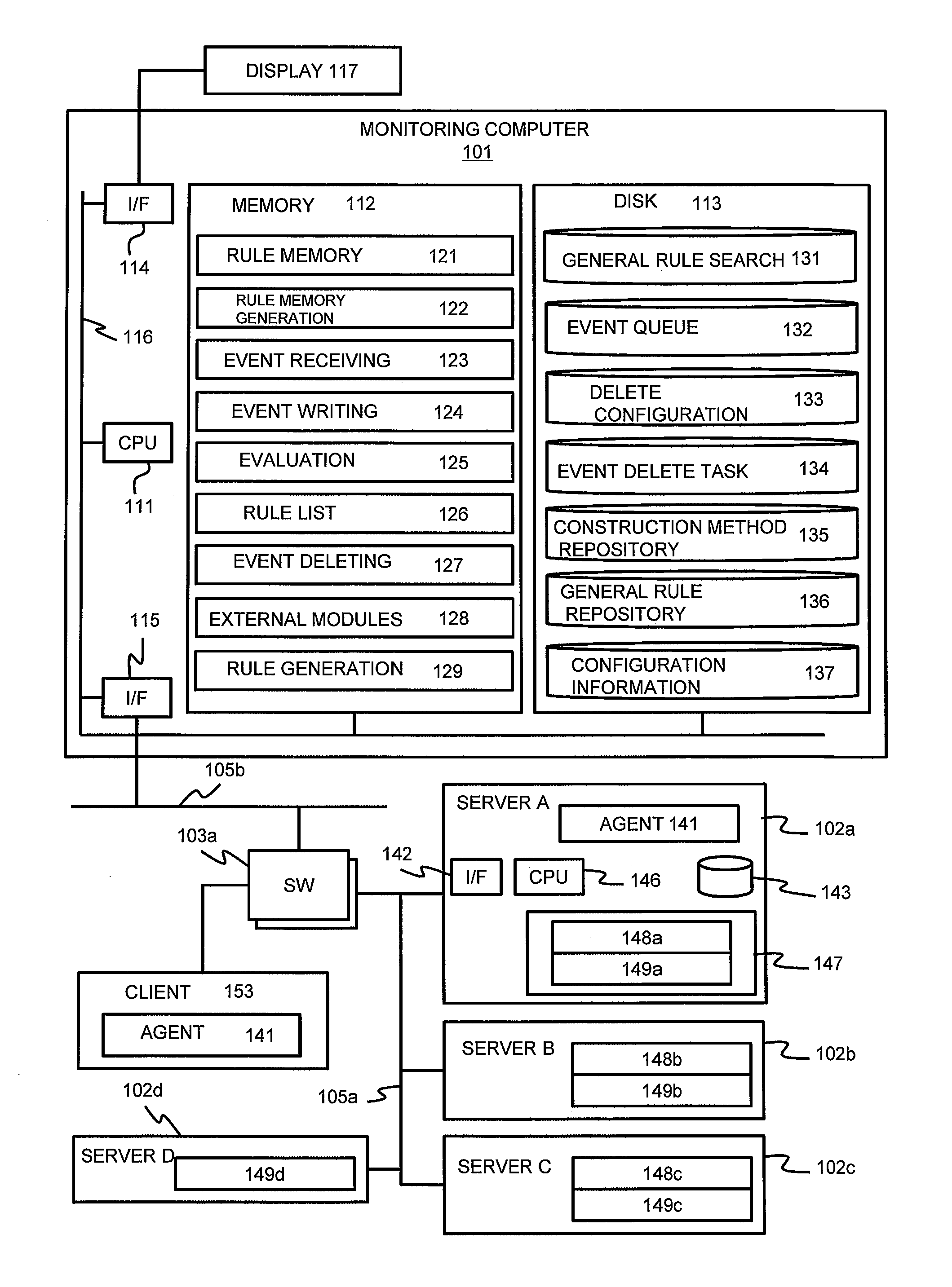
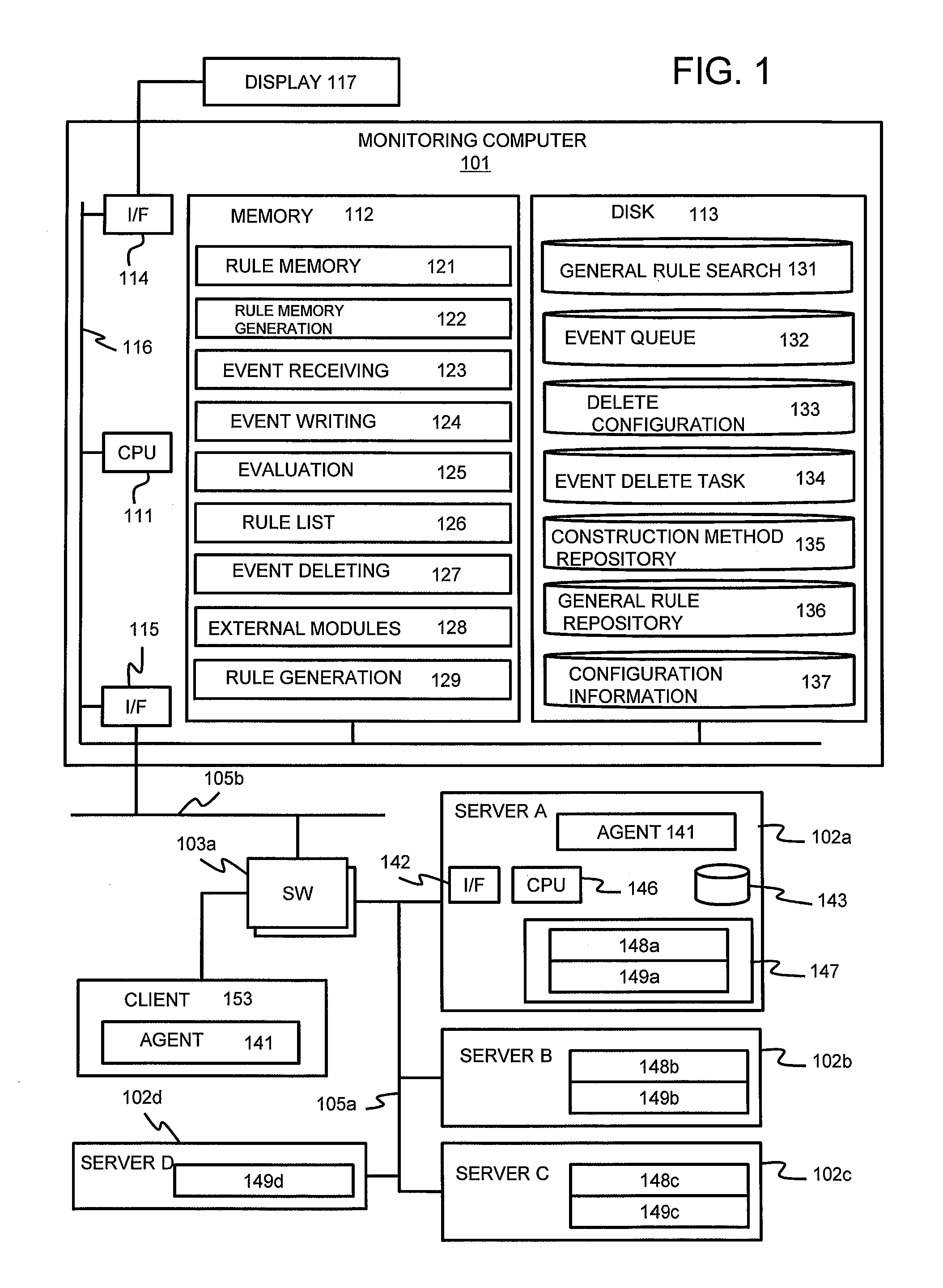
[0076]FIG. 1 shows exemplary hardware and logical composition of an information system which can implement an embodiment of the present invention. In the figure, names of the components are abbreviated as required.

[0077]The system of FIG. 1 includes a monitoring computer 101, one or more network switches or other network apparatus 103, one or more computers which connect with one another to communicate with one another via a network such as a LAN (Local Area Network) 105 or other computers 102.

[0078]The monitoring computer 101 may be a general-purpose computer including a CPU 111, a memory 112, a storage medium such as a hard disk drive (HDD) 113, a video interface 114, and a network interface 115 (I / F) which connects to the monitoring computer 101 via a system bus 116.

[0079]The monitoring computer 101 may be formed with a computer or with a plurality of computers to cooperate with one another. The monitoring computer 101 may include a u...

example 2

[0361]The example 2 will be described. In the example 2, the other correlation rule generation processing and the other matching ratio evaluation processing will be described.

[0362]In the example 1, correlation rules are generated respectively for all combinations of the managed components with respect to the general rule 400a which indicates that a combination of events of a plurality of managed components is the cause. However, in the case where the correlation rules are respectively generated for all the combinations, the data volume to be generated for the correlation rule list 126 and the correlation rule memory 121 becomes too large, which may cause the lack of capacity of the memory 112. In addition, as the correlation rules for one conclusion element is so many that it takes a long time in calculating the matching ratio for one conclusion element.

[0363]In the example 2, in order to solve the above described problem, structures and generation processing of the correlation rul...


PUM


Abstract

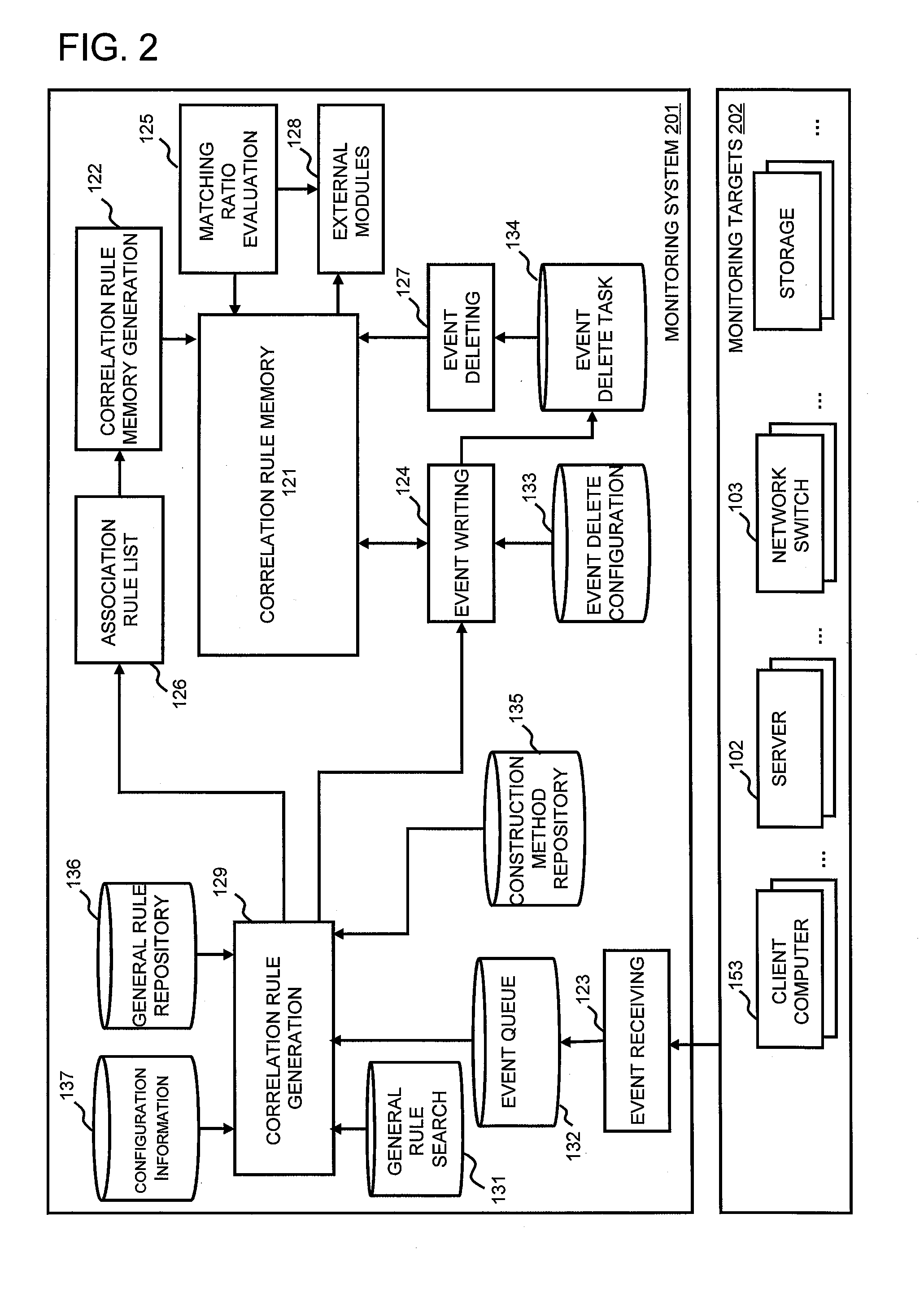
To analyze the cause if an event occurred to a plurality of monitoring targets. A monitoring computer 101 includes a general rule storing part 136 configured to store a general rule, wherein the general rule previously associates a first event which can occur in any of the plurality of monitoring targets and a second event which can cause the first event, an correlation rule generating part 129 configured to generate an correlation rule, wherein the correlation rule is created based on the general rule and configuration information, and in the case where a predetermined number or more of events corresponding to the second events are detected, the correlation rule indicates that an event corresponding to the first event will occur, and an analyzing part 125 configured to analyze a cause of an event indicated by the event information based on received event information and the correlation rule.

Description

TECHNICAL FIELD[0001]The present invention relates to a computer program and a monitoring apparatus.BACKGROUND ART[0002]As various IT (an abbreviation for information technology) apparatuses are connected to one another via networks, IT systems have complicated and scaled up. A fault occurred in an IT system affects the various IT apparatuses over the networks.[0003]As a root cause analyzing technology for identifying the cause place and the cause event of each of these faults, Patent Literature 1 discloses a fault analyzing technology for analyzing fault descriptions received from the IT apparatuses for the root cause place and the cause event of the fault. When an IT apparatus has a fault, it notifies the computer of the fault as event information.[0004]In a conventional fault analyzing technology, a control program configured to analyze a fault accumulates various status information (particularly fault information) of controlled apparatuses in an event DB (database) as events.[00...

Claims


Application Information

Patent Timeline
IPC IPC(8): H04L12/26
CPCH04L43/00H04L41/0631H04L41/065
Inventor MURASE, KAORINAGURA, MASATAKANAGAI, TAKAYUKIKURODA, TAKAKIHOSHINO, KAZUYOSHI
Owner HITACHI LTD
Learn More