
A Secure Virtual Network Layer and Virtual Network Manager that Establishes a Comprehensive Business Reporting and Security Infrastructure as an Integral Part of the Network

a security infrastructure and network layer technology, applied in the field of secure virtual network layer and virtual network manager, can solve the problems of significant separation and variations, impact of outages, security breaches, malicious activities, etc., and achieve the effects of reducing the value of a competitor's equipment, ensuring security and privacy, and high value secure services

Inactive Publication Date: 2006-11-02
RANDLE WILLIAM M +1
View PDF14 Cites 83 Cited by
  • Summary
  • Abstract
  • Description
  • Claims
  • Application Information

AI Technical Summary

Benefits of technology

[0019] By establishing a layer on top of the traditional network transport that integrates a comprehensive security and management reporting capability the solution can assure that all network activity meets a minimum security and business reporting model. Depending on the application or web service this may be accomplished without requiring changes to any application or web service provisioned by the solution of the invention. Applications / web services connected to the invention utilize this layer for secure communication over any network transport by way of a Virtual Service Connection (“VSC”) created and managed by the invention. All traffic inherits a base security model enforced by VSCs. Multiple VSCs are created as needed to create a Virtual Service Network (“VSN”) on top of any transport. This allows for the creation and management of secure VSN and / or multiple VSN communities. VSCs are defined and created through service definitions in the invention and can vary in granularity based on a service providers need.
[0022] The benefits of the invention include all of the elements around secure and auditable information exchange discussed herein as well as the ability to deliver high value secure services over any network transport in one or more governance models. This solution alleviates the need for a dedicated network drop for every network participant, business partner type, or high value application or business function and addresses the fragmented security issues inherent to current approaches. The network drop is replaced by a VSC which is a private virtual connection between one or more participants specific to the participants and the service where comprehensive security and reporting is implemented consistently and specific to that VSC. The invention allows service providers to provide any number of isolated VSCs over any shared network transport including the internet, private networks, wired and wireless connections. In addition service providers can broker services (VSCs) to other participants while maintaining security and privacy with business reporting.
[0024] With SSN a VSC is created specific to the activity and participants for that activity that is open for the duration of the activity and then disposed of. The VSC can be tied to a Service Definition where a Service Definition can be tied to business functions, applications, web services, admin functions, reporting functions, and the like. For example, a service definition may be a web services, can be a VSC specific to an existing web enabled application, can be a web service linked to a legacy application, business function, or business process, can be a web service linked to another web service and the like. In this manner the invention allows for the integration of many disparate systems into a secure comprehensive or simple service that can be universally and securely shared with anyone having access to SSN.

Problems solved by technology

However, as with all good things, there are drawbacks and networked communications is no exception.
As the dependency on networks has become greater so has the impact of outages, security breaches, malicious activities, and cost of support.
This anarchy is largely the result of a lack of a business reporting infrastructure, and the lack of a consistent implementation for comprehensive end to end security that at a minimum includes integrated authentication, authorization, encryption, and end to end logging.
However, with the proliferation of users and devices to the tens of thousands and over a world wide geographical footprint, companies and network providers find themselves faced with a security nightmare that has a fatal characteristic.
That fatal characteristic is the fact that as the number of participants grows there is a parallel relationship between cost and risk, where cost goes up with risk, and risk goes up with the number of participants, number of functions / applications on the network.
Some approaches rely on a private network, other rely on application connected to the network, and most rely on an inconsistent mix of both.
The result is that there is a significant separation and variations in implementation of critical components of security across the layers of the OSI stack with no consistent integration for security and business reporting.
The internet has done a great job of standardizing network connectivity, but does not address comprehensive security or business reporting.
At the lower traditional network levels your network is only as secure your weakest network on-ramp and once someone is on the network there is a very limited capability to know who they are or what they are doing.
These approaches are costly and severely limit participants on the network as well as networked applications.
Today there are many pieces of technology available to implement each of these artifacts, but, there is no integrated solution offering that allows the implementation, management, provisioning, and business reporting on these elements as a function of a virtual network connection and / or a virtual network topology.
However in a mixed user / application environment the result is that your security is only as good as your weakest application.
One common limitation of this approach involves the method of authentication when the network is public and not restricted to a limited set of users.
A common problem in the case of a simple user ID and password configuration for an application over a multi-user network like the internet is that there is no strong method for authenticating the user and the provider.
If the user ID and password is compromised one has no way of telling the real user from a fraudulent one.
Today there is no solution that implements comprehensive security as a prerequisite to establishing a network initiated activity that is transparent to the application(s) using the Network.
The result is that currently there is no method to accomplish all of these security elements where they are implemented and enforced in a consistent manner independent of the network transport provider and / or applications attached to the network where each participant can maintain secure control of their services independent of others on the network.

Method used


Image

  • A Secure Virtual Network Layer and Virtual Network Manager that Establishes a Comprehensive Business Reporting and Security Infrastructure as an Integral Part of the Network
  • A Secure Virtual Network Layer and Virtual Network Manager that Establishes a Comprehensive Business Reporting and Security Infrastructure as an Integral Part of the Network
  • A Secure Virtual Network Layer and Virtual Network Manager that Establishes a Comprehensive Business Reporting and Security Infrastructure as an Integral Part of the Network

Examples


example 1

Base SSN Relationships Model—Simple Requestor and Service Provider

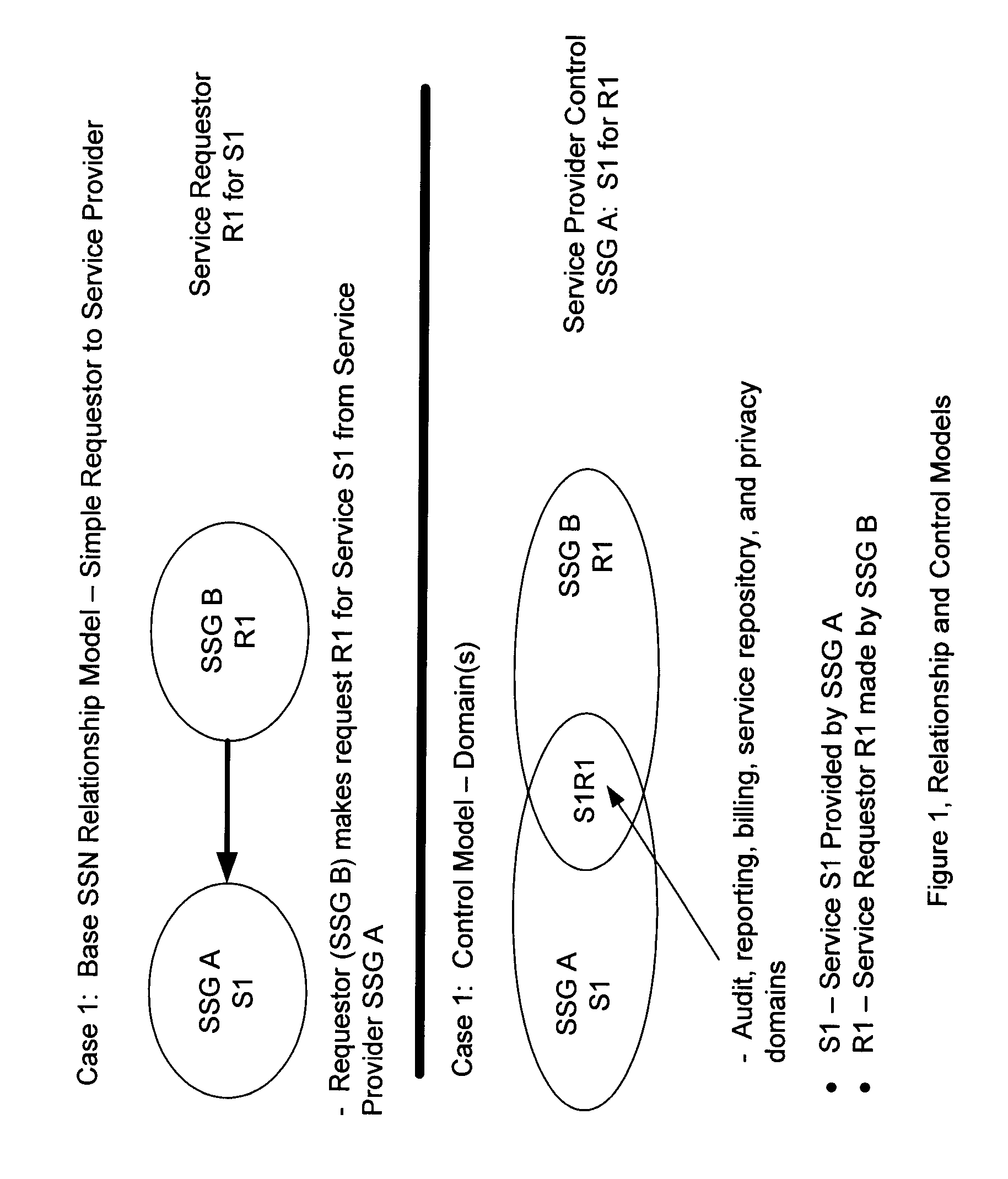
[0124]FIG. 1 depicts relationship and control models for a simple SSN relationship. FIG. 1A illustrates the base SSN relationship model showing a simple requestor communicating to a service provider, namely, requestor SSG B makes a request R1 for a service S1 from service provider SSG A. This represents an example of a simple VSC for the service S1 provided by SSG A.

[0125] This figure displays a relationship model depicting a simple relationship allowed and enforced by the invention and represents a simple VSC. In this case an SSG A on the SSN is a provider of service S1 to the network and specifically granted access to this service to SSG B. SSG B consumes this service by way of a service request R1.

[0126] The control model for the relationship defined by this service is shown in the figure as the domain of S1R1 where the provider of S1 maintains absolute control even though reporting is a combination of SSG A and...

example 2

Multi-User With Privacy—Multi-Services / Multi-Requestor Complete Privacy

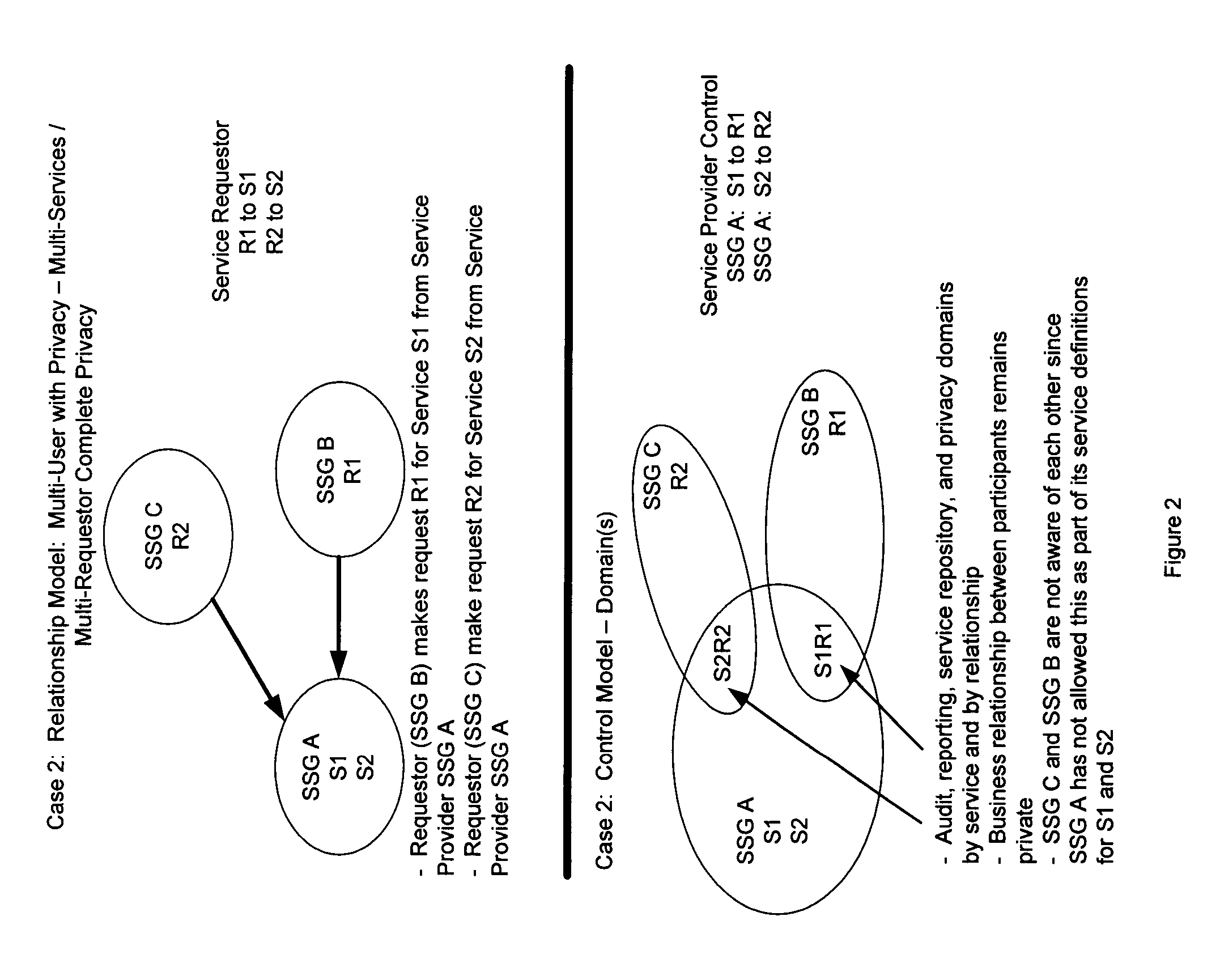
[0136]FIG. 2 depicts a relationship model with multiple users and a privacy function allowing complete privacy for the multiple services and multiple requesters on an instance of the invention. In the control model the business relationship between participants remains private; SSG C and SSG B are not aware of each other since SSG A has not allowed this as part of its service definitions for S1 and S2 for each requester.

[0137] This figure displays a relationship model depicting a multi-user environment allowed and enforced by the invention. In this case the service provider provides a service to one or more requesters—Requestor (SSG B) makes request R1 for Service S1 from Service Provider SSG A;—Requestor (SSG C) makes request R2 for Service S2 from Service Provider SSG A.

[0138] The control model for the relationship defined by this service is shown in the figure as the domains of S1R1 and S2R2 where the provi...

example 3

Multi-User With Privacy—Single Service / Multi-Requestor Complete Privacy

[0139]FIG. 3 depicts a relationship model that provides multiple users with privacy when using the same service from a common service provider where complete privacy is maintained for the requesters. The service requesters are shown R1 to S1 and R2 to S1. Requestor SSG B requests R1 for service S1 from service provider SSG A; requestor SSG C requests R2 for service S1 from service provider SSG A.

[0140] This figure displays a relationship model depicting a multi-user environment allowed and enforced by the invention. In this case the service provider provides a service to one or more requestors—Requestor (SSG B) makes request R1 for Service S1 from Service Provider SSG A;—Requestor (SSG C) makes request R2 for Service S1 from Service Provider SSG A.

[0141] The control model for the relationship defined by this service is shown in the figure as the domains of S1R1 and S1R2 where the provider maintains absolute co...


PUM


Abstract

A Secure Service Network (SSN) in which at least two participants having a relationship are connected to a physical network by way of Secure Service Gateways and share information defined by one or more Service Definitions allowing for the creation of a secure Virtual Service Connection (VSC) between the participants in which the VSC is specific to the activity being performed and the participants provisioned for that activity. SSN enables the creation of a secure virtual network topology on any network transport that allows participants to exchange documents and transact business over the network real time, where all activity inherits a business and security infrastructure that is independent and in addition to the applications, devices, web services, users using the network.

Description

RELATED APPLICATIONS [0001] This application is related to and claims all benefits under 35 U.S.C. § 119(e) of our earlier United States Provisional Patent Applications Ser. No. 60 / 679,295 filed on May 9, 2005, entitled “A Carrier Independent Multipurpose Network with an Embedded Secure Services Layer that Establishes a Business and Security Infrastructure as an Integral Part of the Network.” and Ser. No. 60 / 694,456 filed Jun. 27, 2005, entitled “Service Oriented Network Managed Service Infrastructure and Process Model for Secure Networked Communications With Peer to Peer Functionality”. This present application is a continuation-in-part of co-pending applications Ser. No. 11 / 355,861 filed Feb. 16, 2006 entitled “Secure Digital Courier and Desktop Architecture for Secure Service Oriented Networking”; Ser. No. 11 / 337,394 filed Jan. 23, 2006, entitled “Common Authentication Service for Network Connected Applications, Devices, Users, and Web Services”; Ser. No. 11 / 298,121 filed Dec. 9,...

Claims


Application Information

Patent Timeline
IPC IPC(8): G06F15/16
CPCG06F2221/2145H04L63/0272H04L63/166H04L63/0869H04L63/0823
Inventor RANDLE, WILLIAM M.ORKIS, RANDALL E.
Owner RANDLE WILLIAM M
Learn More