
Austenitic stainless steel welding wire and welding structure

Active Publication Date: 2006-11-02
NIPPON STEEL STAINLESS STEEL CORP
View PDF18 Cites 43 Cited by
  • Summary
  • Abstract
  • Description
  • Claims
  • Application Information

AI Technical Summary

Benefits of technology

[0012] In view of the problems of the conventional technique described above, one of the objects of the exemplary embodiments of the present invention is to provide a highly corrosion-resistant austenitic stainless steel welding wire and welding structure that can be applied to a hull, a bulkhead, a frame, a hydrofoil, etc., of a hull structure that is preferred to have durability in seawater environment and safety against collision and that includes a base metal and a weld zone that are excellent in pitting corrosion resistance and crevice corrosion resistance in seawater environment and excellent in low-temperature toughness.
[0013] The component composition of a weld metal excellent in low-temperature toughness and corrosion resistance in seawater environment by conducting a gas shield arc welding test has been considered by using austenitic stainless steel solid wires and flux-cored wires having various component compositions.
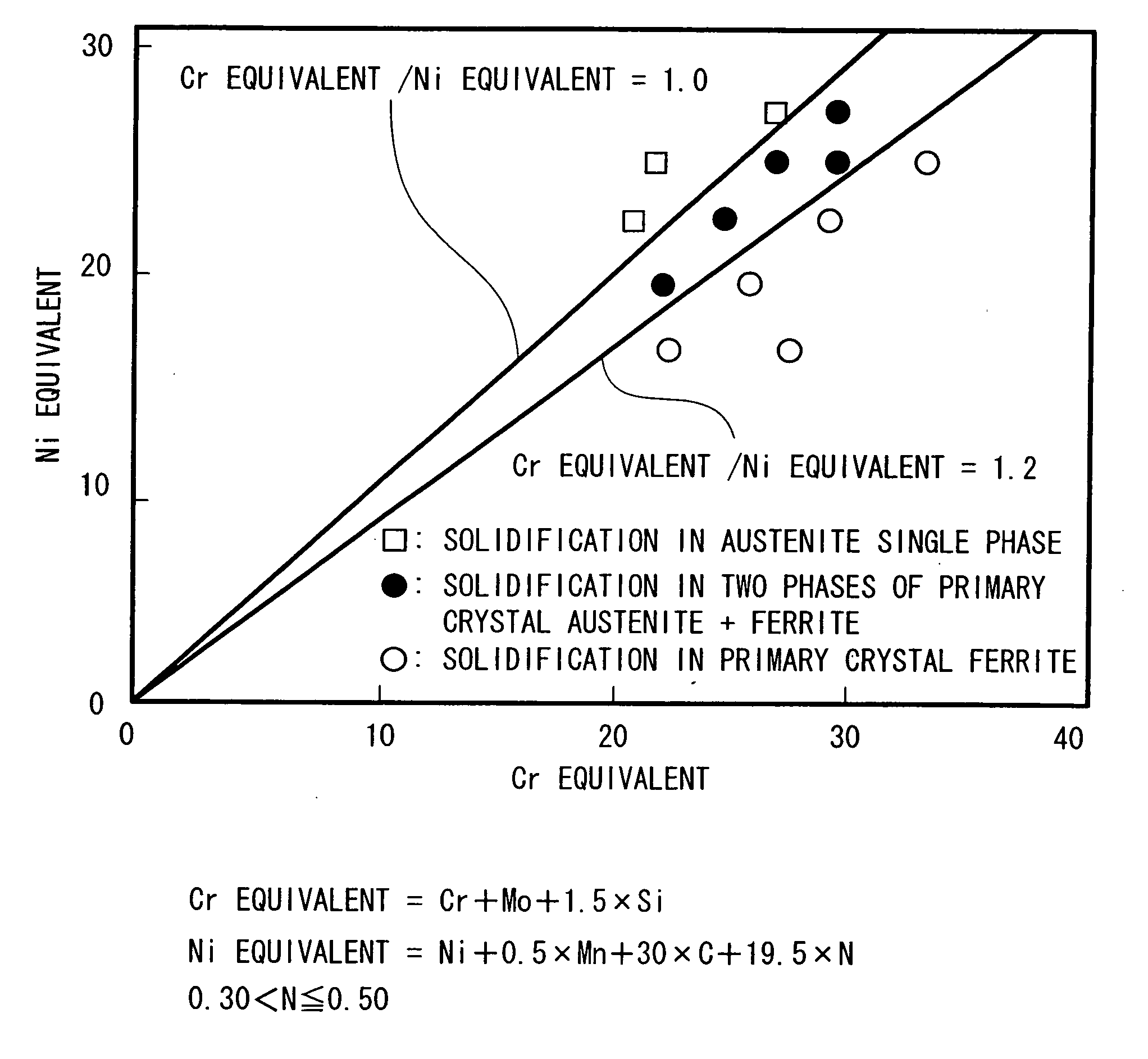
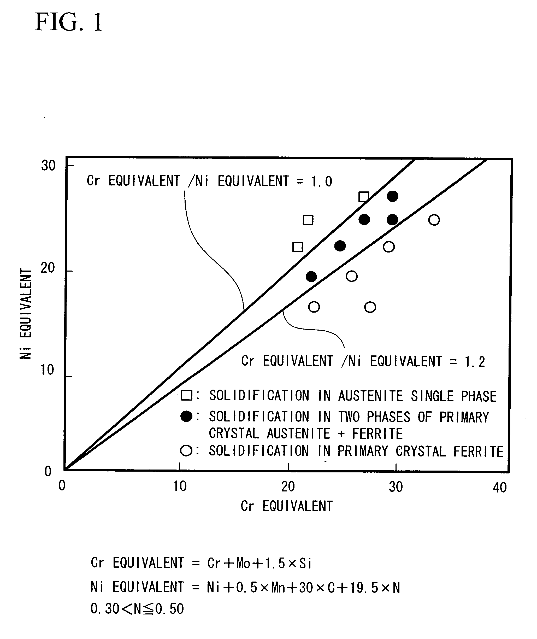
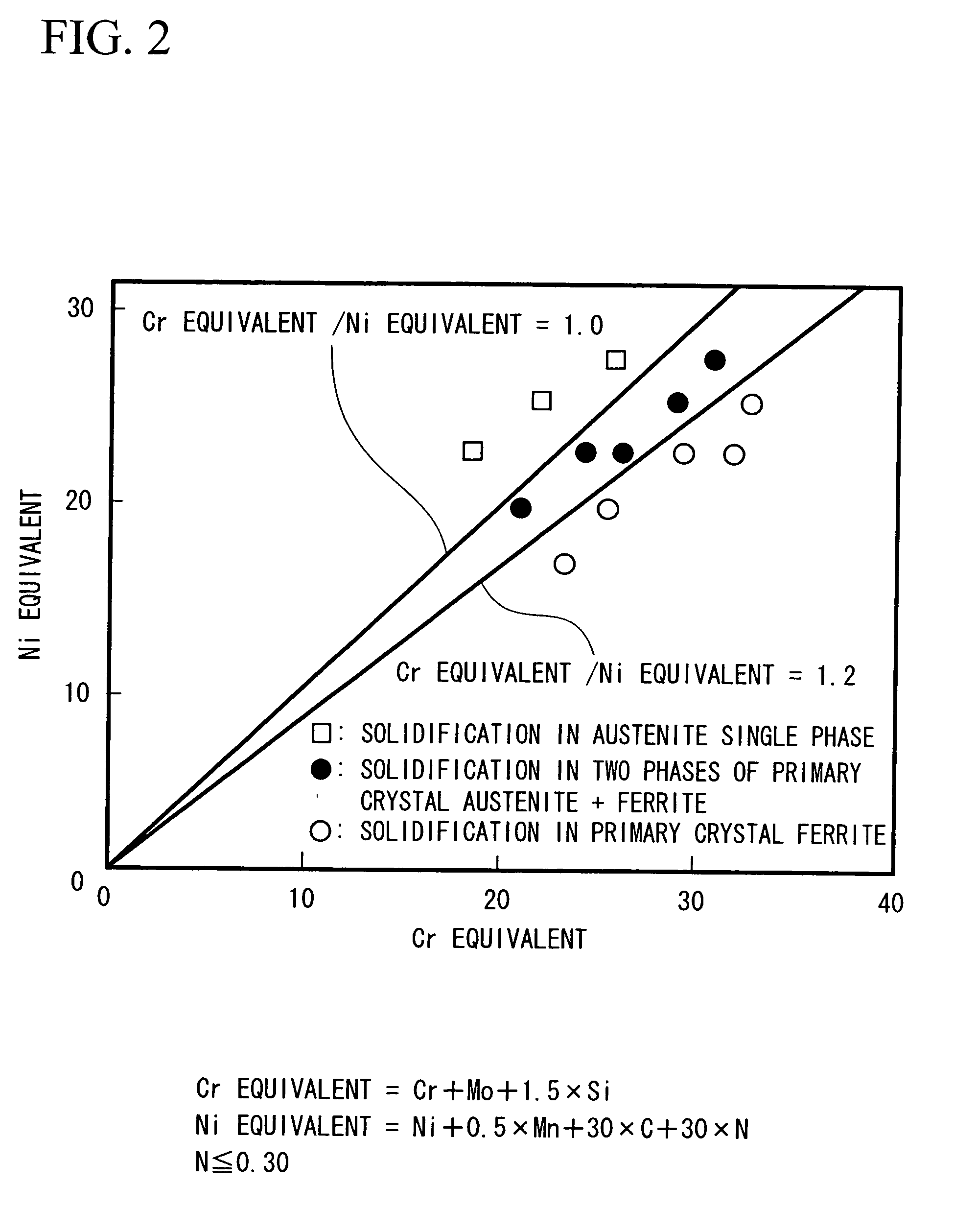
[0014] As a result, an effective method may be provided in which, in order to reduce the ferrite phase that harmfully influences the low-temperature toughness in the weld metal to a degree that does not cause high-temperature solidification cracks and to improve the low-temperature toughness of the weld metal, the component composition of the weld metal is set so that the Cr equivalent / Ni equivalent of the weld metal satisfies 0.85 through 1.2, and in order to improve pitting corrosion resistance of the weld metal in seawater environment, the PI value of the weld metal is set to 35 or more.

Problems solved by technology

However, a brittle phase such as a sigma phase is deposited in the weld metal due to a heat cycle caused by welding and significantly lowers the toughness of the weld metal, and in particular, this problem becomes apparent as the Mo content in the wire increases (for example, refer to Onzawa, et. al., Quarterly Journal of the Japan Welding Society Vol. 5 (1987), pp.
However, weld metal containing a ferrite phase in its weld metal composition becomes lower in low-temperature toughness than a single austenite phase weld metal, and according to an increase in the ferrite amount, this problem becomes apparent (for example, refer to D. T. Read et. al

Method used


Image

  • Austenitic stainless steel welding wire and welding structure
  • Austenitic stainless steel welding wire and welding structure
  • Austenitic stainless steel welding wire and welding structure

Examples


Embodiment Construction

[0012] In view of the problems of the conventional technique described above, one of the objects of the exemplary embodiments of the present invention is to provide a highly corrosion-resistant austenitic stainless steel welding wire and welding structure that can be applied to a hull, a bulkhead, a frame, a hydrofoil, etc., of a hull structure that is preferred to have durability in seawater environment and safety against collision and that includes a base metal and a weld zone that are excellent in pitting corrosion resistance and crevice corrosion resistance in seawater environment and excellent in low-temperature toughness.

[0013] The component composition of a weld metal excellent in low-temperature toughness and corrosion resistance in seawater environment by conducting a gas shield arc welding test has been considered by using austenitic stainless steel solid wires and flux-cored wires having various component compositions.

[0014] As a result, an effective method may be provi...


PUM


Abstract

A welding wire for austenitic stainless steel welding contains, in percent by mass, C: 0.005 through 0.05%, Si: 0.1 through 1.0%, Mn: 1.0 through 3.5%, Cr: 25.0 through 28.0%, Ni: 16.0 through 23.9%, Mo: 1.6 through 3.0%, Cu: 0.1 through 0.5%, Al: 0.001 through 0.02%, and N: more than 0.30 through 0.50%, limiting 0 to 0.03% or less, P to 0.03% or less, and S to 0.005% or less, and having a ratio of a Cr equivalent to Ni equivalent (Cr equivalent / Ni equivalent) within a range between 0.85 and 1.2 and a PI value of 35 or more, the remainder being iron and unavoidable impurities.

Description

CROSS REFERENCE TO RELATED APPLICATION(S) [0001] The present application claims priority from Japanese Patent Application Nos. 2005-118480, 2005-118609, 2005-295584, 2005-295585 and 2005-295, filed Apr. 15, 2005, Apr. 15, 2005, Oct. 7, 2005, Jul. 10, 2005 and Nov. 10, 2005, respectively, under 35 U.S.C. § 119. The entire disclosures and content of these patent applications are incorporated herein by reference. FIELD OF THE INVENTION [0002] The present invention relates to a highly corrosion-resistant austenitic stainless steel welding wire and a welding structure to be used under marine and coastal environments and chloride environments, and more particularly, to a highly corrosion-resistant austenitic stainless steel welding wire and a welding structure by which weld metals excellent in corrosion resistance and crevice corrosion resistance in seawater environment and excellent in low-temperature toughness are obtained when assembling a hull, a bulkhead, a framework, a hydrofoil, et...

Claims


Application Information

Patent Timeline
IPC IPC(8): B23K35/22
CPCB23K35/26
Inventor INOUE, HIROSHIGEHONMA, RYUICHIMIZUMOTO, MANABUOIKAWA, YUUSUKEMATSUHASHI, RYOTSUGE, SHINJIFUKUMOTO, SHIGEO
Owner NIPPON STEEL STAINLESS STEEL CORP
Learn More