
Instant water heater with PTC plastic conductive electrodes

a technology of conductive electrodes and water heaters, which is applied in the direction of fluid heaters, lighting and heating apparatus, and immersion heating arrangements. it can solve the problems of short product life, dry fire burnout, and instant water heaters, and achieve the effect of lowering the outlet temperature of water

Inactive Publication Date: 2006-10-26
CHAPUT IVANHOE
View PDF13 Cites 14 Cited by
  • Summary
  • Abstract
  • Description
  • Claims
  • Application Information

AI Technical Summary

Benefits of technology

[0030] According to a preferred but optional feature of the invention, the polymer electrode is loaded with graphite or graphite nodules, fibers, fibrils and / or nano-fibers to reduce the bulk electrical resistance of the material and provide suitable conductivity for the electrode.

Problems solved by technology

Presently-known instant water heaters do have major disadvantages, including short product life, dry-fire burn-out, short service life, liability to water damage, moderate rates of flow, high energy consumption, and release of metal ions into the water.
Another disadvantage of existing instant water heaters is their inability to accommodate varying input voltages and amperage along with water flow that matches their intended use.
A complaint often heard is that the wrong instant water heater was purchased from many different models.
The necessary wide range of variables, such as voltage and circuit breaker amperage, and service flow in gallons is simply too confusing for many customers.
It is yet another disadvantage of existing instant water heaters that they often burn out or break coils due to water hammering, air in the water lines, or current overloads.
These pose an electrical danger from direct contact of live broken coil ends to the water.
Manifolds that are connected to ground with a grounding wire corrode, and it is only a matter of time before a corroded manifold or a burned out coil releases a full current into the water and out a faucet or other plumbing fixture when in use, to the risk of the user.
It is a disadvantage of conventional electrode water heaters to have to contend with the wide variation of water conductivity of drinking water, both in the United States and in other parts of the world.
The disadvantage occurs when their electrodes must be sized such that they are capable of attaining satisfactory performance with 50 microsiemen water, but must then regulate a potentially hazardous 30 times the current draw when the water is at 1,500 microsiemens.
Since prior to this invention, electrodes could not be resized on the fly, regulating this amount of power has been costly.
However, to regulate the high current potentials of electrode water heaters, these methods are economically and technically unacceptable.
It is yet another disadvantage of electrode water heaters that suggest methods of power regulation using said wave-chopping devices, that such devices can introduce harmonics in the line and heat the wiring without tripping the circuit breaker.
Wires can become extremely hot, causing serious fire hazard.
However, current matching for electrode water heaters and boilers is nearly impossible to accomplish with such a widely varying electrical load without mechanically moving the electrodes as is done in large, expensive industrial electrode boilers.
To do this in a home appliance such as an instant water heater would be too costly and would introduce wear parts that would greatly increase the failure modes of the device.
Yet another disadvantage of electronically regulating high current via AC wave chopping is the electromagnetic emissions that disrupt communications television signals and create radio static interference.
These emissions are not allowed in Europe's “Flicker Standard” and can violate FCC regulations.
It is another disadvantage of electrode water heaters that in order to match the load to the line without the said expensive sine wave chopping devices, the preferred method is to physically move the electrodes via electric motors.

Method used


Image

  • Instant water heater with PTC plastic conductive electrodes
  • Instant water heater with PTC plastic conductive electrodes
  • Instant water heater with PTC plastic conductive electrodes

Examples


Embodiment Construction

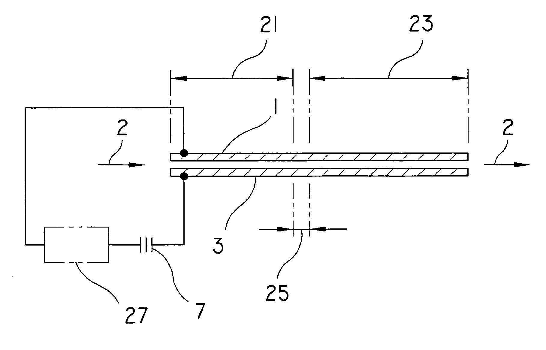
[0052] Although this invention contemplates a number of physical arrangements for effective heating and for regulation of electrical current so as not to induce undesirable harmonics that can over heat electrical wiring, the principal advantages of this invention are derived from the use of unique PTC electrodes which they all use.

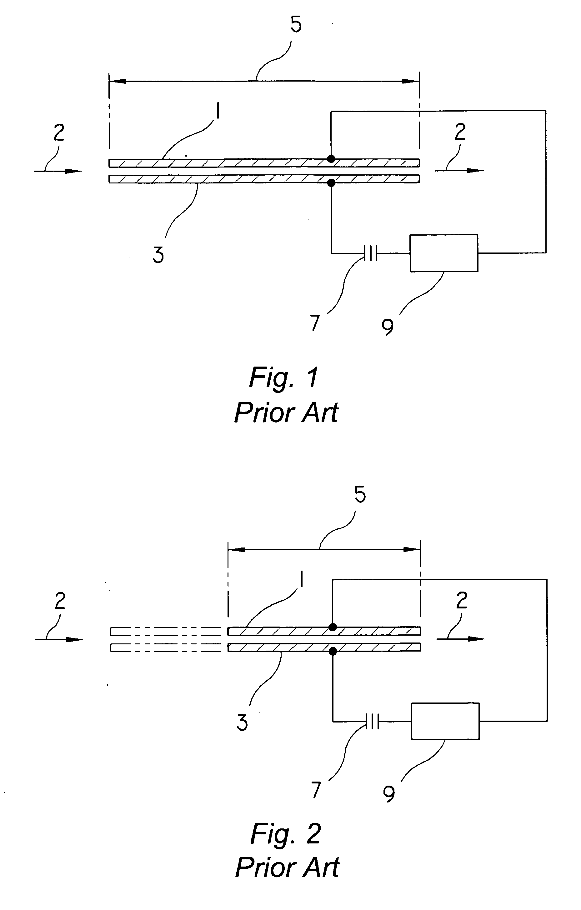
[0053] A basic schematic of a prior art electrode water heater is shown in FIG. 1 (Prior Art). Water flows 2 between two electrodes 1,3 while power 7 is regulated by way of an electronic circuit 9 to provide a pre-selected water temperature based on a combination of the water's electrical conductivity and the area of the opposed faces 5 of said electrodes 1,3.

[0054] Should the water conductivity become extremely high, a solution shown in FIG. 2 (Prior Art) for stopping a overcurrent condition would be to shorten the electrodes thereby reducing the area of their said opposed faces 5 such that it would better match the available power to the water's conduc...


PUM


Abstract

An instant water heater utilizing positive temperature coefficient plastic electrically conductive material structures for electrodes. The heating of the water is not generated by the electrodes, but instead by the resistance of the water to the electrical current flowing between them. The material of the electrodes undergoes a phase change at certain temperatures when whereby it converts from electrically conductive to electrically non-conductive at a predetermined temperature. The output temperature of the water is determined by a combination of the area of the electrodes that confront one another, the water's conductivity, the flow rate of the water and the current limiting capability of the conductive electrode materials positive temperature coefficient, which reduces or stops the heating of the water when the intended water temperature is achieved.

Description

FIELD OF THE INVENTION [0001] An instant water heater which heats water flowing between two immersed electrodes. BACKGROUND OF THE INVENTION [0002] This invention relates to water heaters of the type which heat water that flows between two electrodes, rather than by providing a hot element which is contracted by the water. In this invention, the water is heated by electrical current flowing through the water when the water is between the two electrodes. [0003] So called “instant” water heaters differ from conventional water heaters by their lack of a storage tank for hot water. Instead of heating and storing water for future usage, instant water heaters accept cold or cool water, heat it, and deliver it directly to the user point on demand. Such heaters find their most common usage in sink faucets, showers and tube, although they can be provided for any other usage that requires hot water. [0004] Among their advantages is that they can be placed very near to the use point. Pipes of ...

Claims


Application Information

Patent Timeline
Patent Type & Authority Applications(United States)
IPC IPC(8): F22B1/30H05B3/60
CPCA47J27/21025H05B2214/04F24H1/106
Inventor CHAPUT, IVANHOE
Owner CHAPUT IVANHOE
Learn More