
Bearing apparatus for a driving wheel of a vehicle

a technology for bearings and driving wheels, which is applied in mechanical devices, rigid supports of bearing units, transportation and packaging, etc., can solve the problems of affecting the quality of assembled products, causing torsional deformation in the drive shaft, etc., and achieves the effects of ensuring the quality of bearing apparatus, preventing the cover from easily falling out, and improving workability

Active Publication Date: 2006-10-26
NTN CORP
View PDF4 Cites 13 Cited by
  • Summary
  • Abstract
  • Description
  • Claims
  • Application Information

AI Technical Summary

Benefits of technology

[0010] The present disclosure provides a bearing apparatus for a driving wheel of vehicle which substantially prevents, with a simple structure, lubricant, such as grease, applied to the end surface of the inner ring or a caulked portion of the wheel hub from being contacted by a work table. Thus, this prevents the lubricant from being contaminated by foreign matter which enters into the lubricant from the surface of a work table.

Problems solved by technology

Thus, torsional deformation is caused in the drive shaft.
In addition, the quality of the assembled products would be spoiled by foreign matter which enters the grease from the working table

Method used


Image

  • Bearing apparatus for a driving wheel of a vehicle
  • Bearing apparatus for a driving wheel of a vehicle
  • Bearing apparatus for a driving wheel of a vehicle

Examples


Embodiment Construction

[0031] Preferred embodiments of the present disclosure will be described with reference to accompanied drawings.

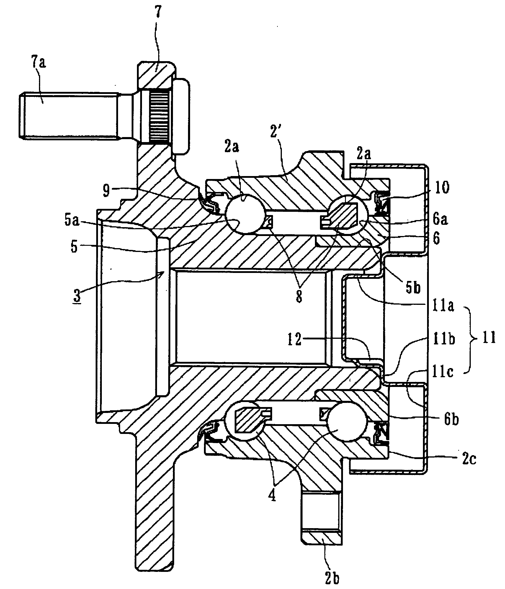
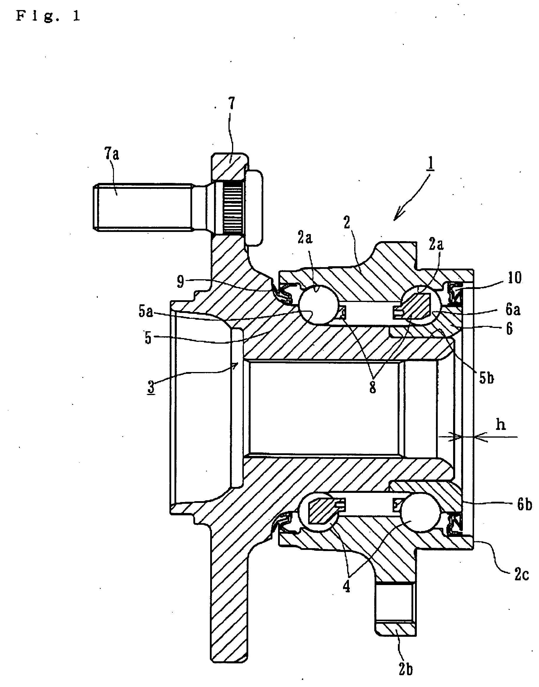
[0032]FIG. 1 is a longitudinal-section view of a first embodiment of a bearing apparatus for a driving wheel of vehicle. In the description below, the term “outboard side” of the bearing apparatus means a side positioned outside of a vehicle body. The term “inboard side” means a side positioned inside of a vehicle body when the bearing apparatus is mounted on the vehicle body.

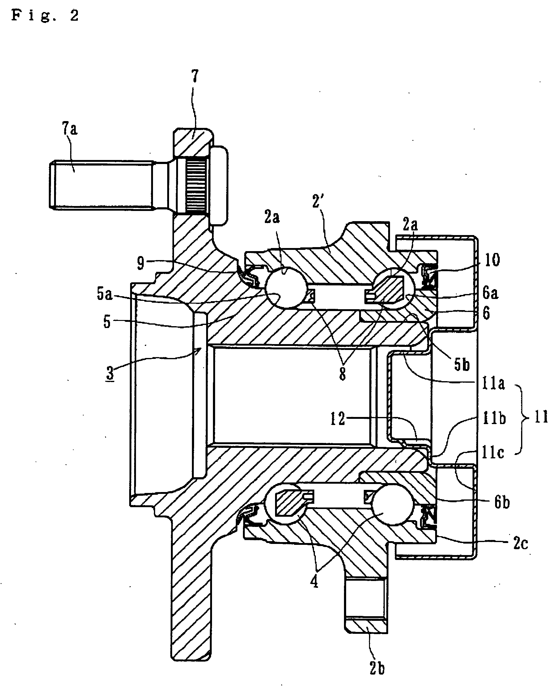
[0033] The bearing apparatus for a driving wheel of a vehicle is formed as a unit including a double row rolling bearing 1 and a wheel hub 5. The double row rolling bearing 1 has an outer member2, inner member 3 and double row rolling elements (balls) 4 contained between the outer and inner members 2 and 3. The inner member 3 includes a wheel hub 5 with an integrally formed wheel mounting flange 7 at one end. The inner member 3 has one of the inner raceway surfaces (outboard side raceway surface) 5a...


PUM


Abstract

A bearing apparatus for a driving wheel of a vehicle has an outer member (2), inner member (5, 6), rolling elements (4), outer joint member (61) and a cover (11, 67). The outer member (2) is formed with double row outer raceway surfaces (2a) on its inner peripheral surface The inner member (5, 6) include a wheel hub (2) with an integrally formed wheel mounting flange (7) at one end and an axially extending cylindrical portion (5b, 13b) of a smaller diameter. At least one inner ring (6) is press fit onto the cylindrical portion (5b, 13b). The inner member (5, 6) is formed with double row inner raceway surfaces (5a, 6a) arranged opposite to the double row outer raceway surfaces (2a). The double row rolling elements (4) are freely rollably contained between the outer and inner raceway surfaces (2a and 5a, 6a). The outer joint member (61) of a constant velocity universal joint (53) is integrally formed with a shaft portion (60) which is inserted into the inner member (5, 6) in a torque transmitting manner and is axially fastened by a nut (63) so that it abuts the inner member (5, 6). Lubricant is applied to the end face of the inner member (6) that abuts the outer joint member (61). The cover (11, 17) is mounted on the end of the inner member (6). The cover (11, 17) has a fitting portion (11a, 17a) adapted to be inserted into the cylindrical portion (5b, 13b) and an annular bottom portion (11c, 17b) to cover the end of the inner member (6).

Description

CROSS-REFERENCE TO RELATED APPLICATIONS [0001] This application claims priority to Japanese Patent Application No. 2005-124589, filed Apr. 22, 2005, which application is herein expressly incorporated by reference. FIELD [0002] The present invention relates to a bearing apparatus for a driving wheel of a vehicle. The bearing apparatus supports a driving wheel of a vehicle, such as an automobile. The bearing apparatus, for the driving wheel of a vehicle, transmits torque and is separably connected to an outer joint member of a constant velocity universal joint. The bearing apparatus is structured as a unit of a wheel hub and a double row rolling bearing. BACKGROUND [0003] The power transmitting apparatus, to transmit the engine power of vehicle to its wheels, transmits power from an engine to the wheels. The power transmitting apparatus enables radial and axial displacement of the wheels and moment variation. Accordingly, a drive shaft interposed between the engine and the driving whe...

Claims


Application Information

Patent Timeline
Patent Type & Authority Applications(United States)
IPC IPC(8): F16C13/00
CPCB60B27/0005B60B27/0084B60B27/0094F16C2326/02F16C33/6614F16C41/04F16C43/04F16C19/186F16C35/0635F16C19/184F16C19/527F16C33/586
Inventor SHIGEOKA, KAZUHISAKAWAMURA, HIROSHI
Owner NTN CORP
Learn More