
Dynamic cathode gas control for a fuel cell system

Inactive Publication Date: 2006-10-19
GM GLOBAL TECH OPERATIONS LLC
View PDF9 Cites 19 Cited by
  • Summary
  • Abstract
  • Description
  • Claims
  • Application Information

AI Technical Summary

Benefits of technology

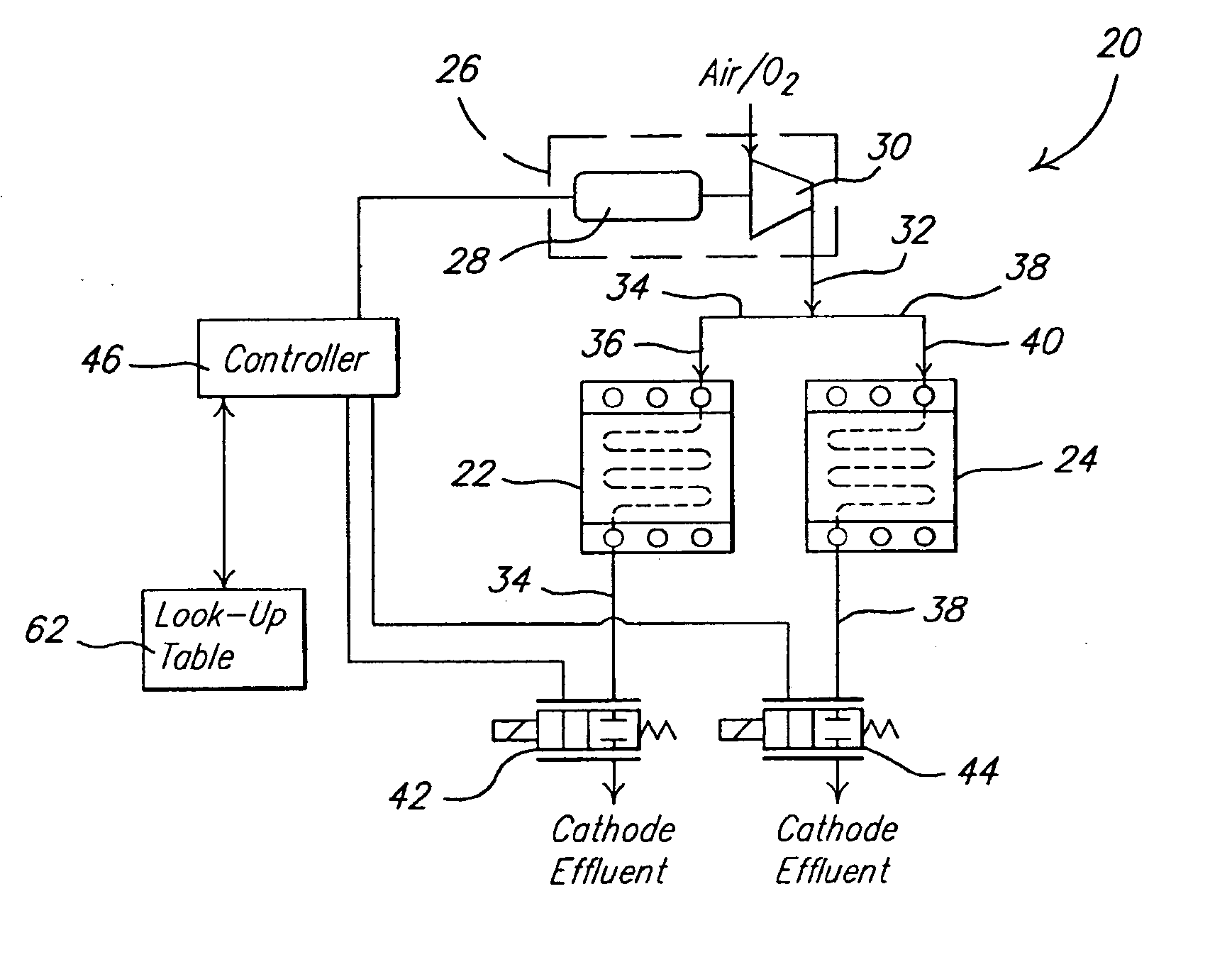
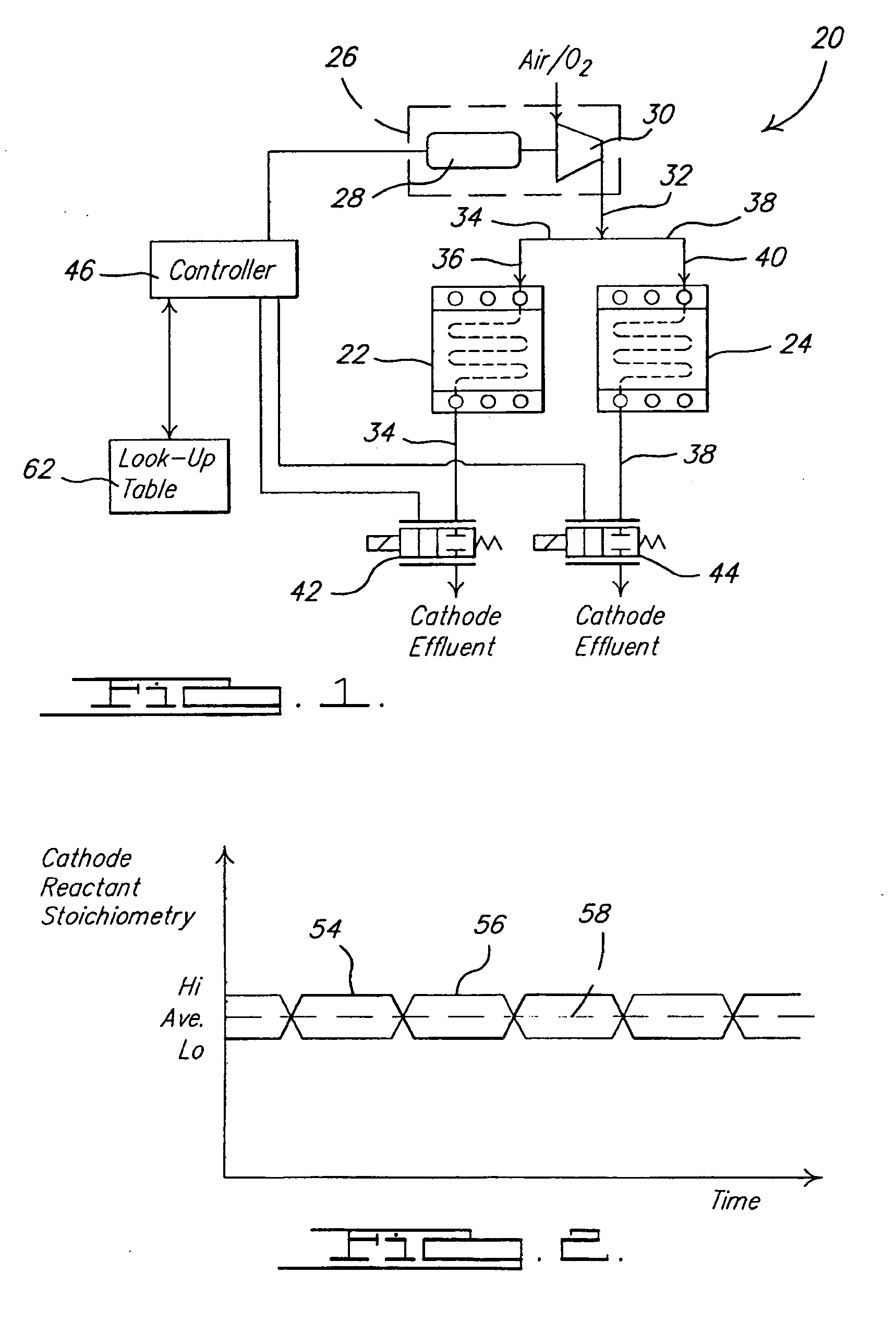
[0006] Typically, when a constant power demand is placed on a fuel cell stack, the fuel cell stack is supplied a constant cathode reactant flow. The cathode reactant flow is typically provided by an airmover, such as a blower or a compressor. The airmover also supplies the cathode reactant flow at a pressure level which is needed by the fuel cell stack and is defined by other operating conditions, such as a fuel cell temperature. The fuel cell stack outlet pressure is controlled by a back pressure valve. When the airmover supplies a constant flow of cathode reactant, the airmover will consume a specific quantity of power. The inventors have discovered that by pulsing the flow of cathode reactant flowing through the cathode side of the fuel cell stack, instead of supplying a constant cathode reactant flow, the required water removal on the cathode side can be satisfied while reducing the average stoichiometric quantity of cathode reactant supplied to the fuel cell stack. The pulsing includes varying the stoichiometric quantity of cathode reactant being supplied to the fuel cell stack between two distinct values. The higher stoichiometric quantity is chosen to satisfy the need for water removal while the lower stoichiometric quantity is selected to be sufficient for the transport of the reactant and stable electricity production. This results in an average stoichiometric quantity of cathode reactant being supplied to the fuel cell stack that is lower than that supplied when not pulsing the cathode reactant. Thus, in the present invention, the average electrical power demand of the airmover is expected to be lower. This lower power demand helps with system efficiency.

Problems solved by technology

When the airmover supplies a constant flow of cathode reactant, the airmover will consume a specific quantity of power.
The adjusting of the airmover between these levels, however, can produce a noise pattern that may be annoying to a user, especially when a constant power demand is placed on the fuel cell system and / or when the fuel cell system is used on a mobile platform.

Method used


Image

  • Dynamic cathode gas control for a fuel cell system
  • Dynamic cathode gas control for a fuel cell system
  • Dynamic cathode gas control for a fuel cell system

Examples


Embodiment Construction

[0017] The following description of the preferred embodiments is merely exemplary in nature and is in no way intended to limit the invention, its application, or uses.

[0018] As used herein, the term module refers to an application specific integrated circuit (ASIC), an electronic circuit, a processor (shared, dedicated or group) and memory that executes one or more software or firmware programs, a combinational logic circuit, or other suitable components that provide the described functionality.

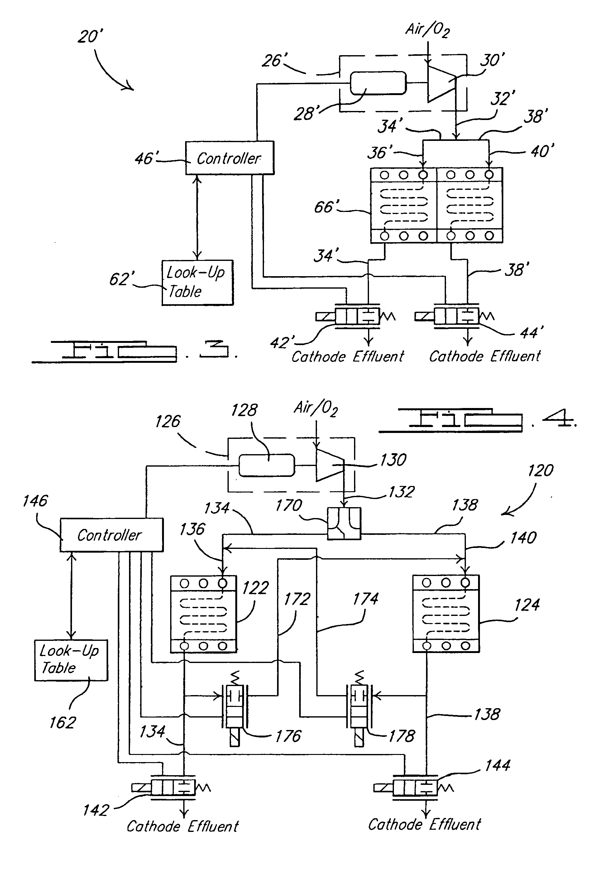
[0019] Referring to FIG. 1, a first preferred embodiment of a fuel cell system 20 according to the principles of the present invention is schematically represented. Fuel cell system 20 includes first and second fuel cell stacks 22 and 24 that each have an anode side and a cathode side for receiving respective hydrogen-containing anode reactant and oxygen-containing cathode reactant. Each fuel cell stack 22, 24 is operable to convert the anode and cathode reactants into electricity, a hydrog...


PUM


Abstract

A fuel cell system utilizes at least one flow restricting device to vary the stoichiometric quantity of cathode reactant flowing to two discrete cathode sides of the fuel cell system. The varying of the stoichiometric quantity of cathode reactant can be between two predetermined values. The varying of the stoichiometric quantity can be during a steady state power demand placed on the system and / or during transients in a power demand placed on the system. The airmover that supplies the cathode reactant stream can be operated in a substantially continuous manner during a continuous power demand placed on the fuel cell system.

Description

FIELD OF THE INVENTION [0001] The present invention relates to fuel cell systems and more particularly to dynamic control of the cathode gas in a fuel cell system. BACKGROUND OF THE INVENTION [0002] H2—O2(air) fuel cells are well known in the art and have been proposed as a power source for many applications. There are several types of H2—O2 fuel cells including acid-type, alkaline-type, molten-carbonate-type, and solid-oxide-type. So called PEM (proton exchange membrane) fuel cells (a.k.a. SPE (solid polymer electrolyte) fuel cells) are of the acid-type, potentially have high power and low weight, and accordingly are desirable for mobile applications (e.g., electric vehicles). PEM fuel cells are well known in the art, and include a “membrane electrode assembly” (a.k.a. MEA) comprising a thin, proton transmissive, solid polymer membrane-electrolyte having an anode on one of its faces and a cathode on the opposite face. The MEA is sandwiched between a pair of electrically conductive ...

Claims


Application Information

Patent Timeline
IPC IPC(8): H01M8/04H01M8/24
CPCH01M8/04089H01M8/04097H01M8/04104Y02E60/50H01M8/04201H01M8/249H01M2008/1095H01M8/04111
Inventor SCHAEFER, ROBERTPECHTOLD, RAINERROHWER, THORSTEN
Owner GM GLOBAL TECH OPERATIONS LLC
Learn More