
System and method for displaying validity of airport visual approach slope indicators

a technology of visual approach slope and display system, which is applied in the field of display system, can solve the problems of limited accuracy and landing safety of lighting system for visually indicating a glide path, limited distance of runway runway, and flight crews to take, so as to improve the accuracy, availability and validity, and improve the safety of aircraft's approach and landing.

Inactive Publication Date: 2006-10-12
HONEYWELL INT INC
View PDF13 Cites 32 Cited by
  • Summary
  • Abstract
  • Description
  • Claims
  • Application Information

AI Technical Summary

Benefits of technology

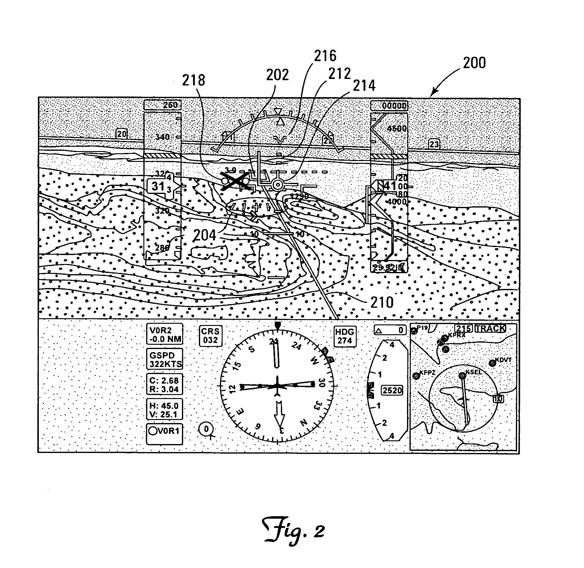
[0012] The present invention provides an improved system and method for indicating the validity of airport visual approach slope indicators on an aircraft display. In accordance with a preferred embodiment of the present invention, an aircraft display system is provided, which includes a database for storing pertinent data associated with the specific visual approach slope lighting indicator system being used by each airport of a plurality of airports and any special distance and / or usage limitations associated with each such visual approach slope indicator system, a processing unit, a position determination unit, and a visual display. As an aircraft approaches an airport, the processing unit receives the aircraft's current position from the position determination unit, and compares the aircraft's current position data with the distance and / or usage limitation data stored in the database for the approach slope indicator system being used by that airport. For this example embodiment, if the processing unit's comparison of the aircraft's current position data and the airport's distance and / or usage limitation data indicates that the visual approach slope lighting indicator system is within a valid range, then the processing unit provides a display format of a simulated airport environment for the airport of interest to the visual display, which includes a symbolic presentation of the airport's visual approach slope lighting indicators associated with the aircraft's current position, along with appropriate colors for the lighting elements being displayed. However, if the processing unit's comparison of the aircraft's current position data and the airport's distance and / or usage limitation data indicates that the visual approach slope lighting indicator system is not within a valid range, then the processing unit provides a display format of a simulated airport environment for the airport of interest to the visual display, which includes a symbolic presentation of the airport's visual approach slope lighting indicators with the lighting elements capped, for example, with a red X symbol. Therefore, by indicating with a simulated visual display the validity or invalidity of an airport's visual approach slope lighting indicators apparently being seen by the flight crew, the present invention significantly improves the accuracy, availability and validity of the approach slope indicator system being used, and the safety of the aircraft's approach and landing.

Problems solved by technology

However, some airports do not have an ILS-generated radio glideslope.
However, a significant problem with the existing airport lighting aids, such as the PAPI, VASI and other visual approach indicators, is that although the approach lighting systems at an airport can be visible at a range of 10 miles or more, the validity of the lighting systems (e.g., in terms of accuracy and landing safety) for visually indicating a glide path is limited to a distance which is less than 5 miles from the airport.
Notably, a recent near-accident of a corporate jet near Scottsdale, Ariz. can be attributed to the flight crew's unawareness or disregard of the variable distance versus lighting system validity problems that affect the accuracy and safety of an airport's approach slope lighting indicator system.
In any event, another significant problem with the existing airport lighting aids is that the compelling nature of the lights can cause flight crews to take an “on glide path” indication at face value, regardless of the aircraft's distance to the airport.
Consequently, if an aircraft is more than 5 miles from an airport, an apparent (to the flight crew) visual indication that the aircraft is on the glide path is likely incorrect (with significant potential airport and landing safety consequences).

Method used


Image

  • System and method for displaying validity of airport visual approach slope indicators
  • System and method for displaying validity of airport visual approach slope indicators
  • System and method for displaying validity of airport visual approach slope indicators

Examples


Embodiment Construction

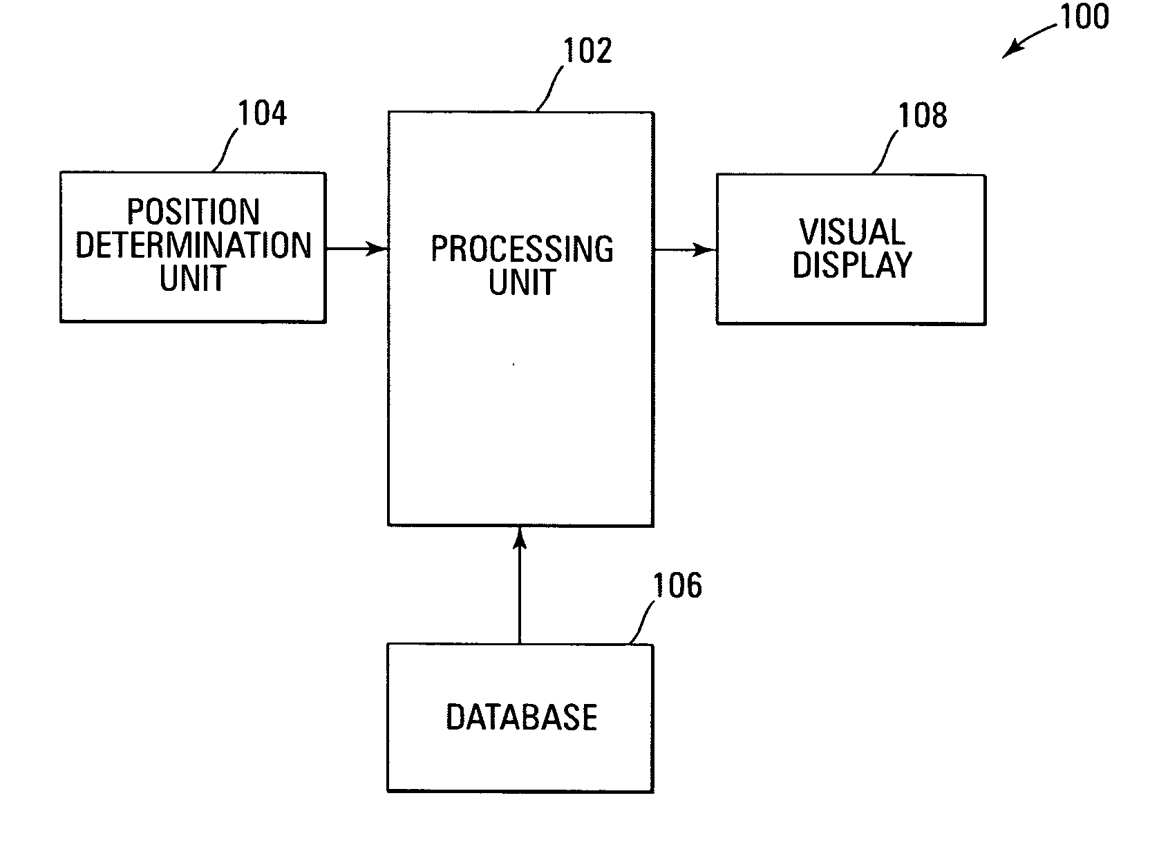
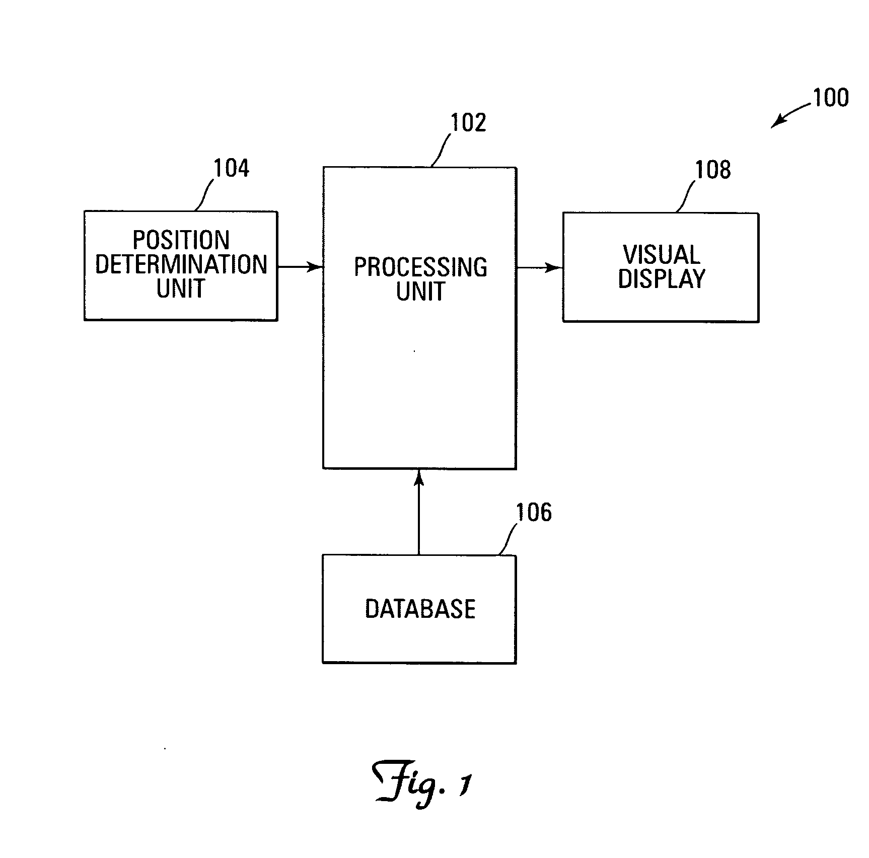
[0019] With reference now to the figures, FIG. 1 depicts a block diagram of an example system 100 for indicating the validity of airport runway visual approach slope indicators on an aircraft display, which can be used to implement a preferred embodiment of the present invention. For this example embodiment, system 100 includes a processing unit 102, a position determination unit 104, a database 106, and a visual display 108. Notably, it should be understood that although system 100 appears in FIG. 1 to be arranged as an integrated system, the present invention is not intended to be so limited and can also include an arrangement whereby one or more of processing unit 102, position determination unit 104, database 106 and visual display 108 is a separate component or a subcomponent of another system located either onboard or external to an aircraft. Also, for example, system 100 can be arranged as an integrated system (e.g., aircraft display system, etc.) or a subsystem of a more com...


PUM


Abstract

An improved system and method are disclosed for indicating the validity of airport runway visual approach slope indicators on an aircraft display. An aircraft display system is provided, which includes a database for storing data about the specific visual approach slope lighting indicator system being used by each airport of a plurality of airports and any special distance and / or usage limitations associated with each such visual approach slope indicator system, a processing unit, a position determination unit, and a visual display. As an aircraft approaches an airport, the processing unit receives the aircraft's current position from the position determination unit, and compares the aircraft's current position data with the distance and / or usage limitation data stored in the database for the approach slope indicator system being used by that airport. If the processing unit's comparison of the aircraft's current position data and the airport's distance and / or usage data indicates that the visual approach slope lighting indicator system is within a valid range, then the processing unit provides a display format of a simulated airport environment for the airport of interest to the visual display, which includes a symbolic presentation of the airport's visual approach slope lighting indicators associated with the aircraft's current position, along with appropriate colors for the lighting elements being displayed. However, if the processing unit's comparison of the aircraft's current position data and the airport's distance and / or usage data indicates that the visual approach slope lighting indicator system is not within a valid range, then the processing unit provides a display format of a simulated airport environment for the airport of interest to the visual display, which includes a symbolic presentation of the airport's visual approach slope lighting indicators with the lighting elements capped, for example, with a red X symbol. Therefore, in this manner, the accuracy, availability and validity of the lighting system, and the safety of the aircraft's approach and landing are significantly improved.

Description

FIELD OF THE INVENTION [0001] The invention relates generally to the field of display systems, and more specifically, but not exclusively, to a system and method for displaying the validity of airport visual approach slope indicators on an aircraft display. BACKGROUND OF THE INVENTION [0002] Techniques for displaying simulated airport visual approach glideslope indicators on aircraft cockpit displays are known. An example of such a technique is disclosed in commonly assigned U.S. Patent Application Publication No. US 2002 / 0099528 A1 to Charles L. Hett (“Hett”), which is incorporated herein by reference in its entirety. As described in Hett, aircraft landing at airports during marginal Visual Meteorological Conditions (VMC) or in situations where there are reduced visual cues (e.g., night flights) are aided by an Instrument Landing System (ILS). An ILS provides a radio beam that originates on the ground at an ILS-equipped airport and generates a glideslope that an aircraft can follow...

Claims


Application Information

Patent Timeline
Patent Type & Authority Applications(United States)
IPC IPC(8): G01C23/00
CPCG01C23/005G08G5/025G08G5/0021
Inventor GANNON, AARON J.
Owner HONEYWELL INT INC
Learn More