
Aspiration and delivery safety system

a delivery safety and delivery technology, applied in the field of blood aspiration and delivery safety systems, can solve the problems of blood from the puncture site infecting the medical person, and medical personnel becoming infected

Inactive Publication Date: 2006-09-07
YANG CHANG MING
View PDF4 Cites 43 Cited by
  • Summary
  • Abstract
  • Description
  • Claims
  • Application Information

AI Technical Summary

Benefits of technology

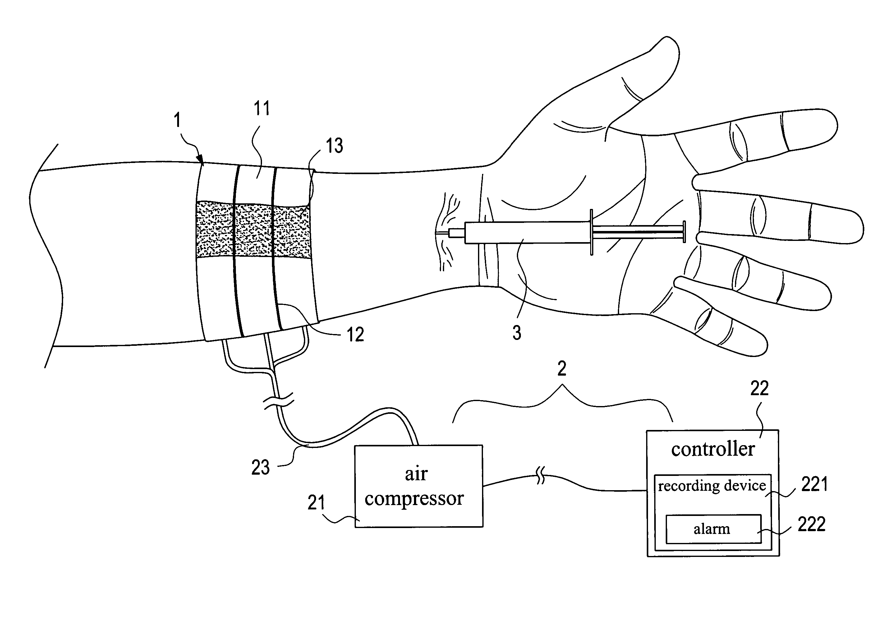
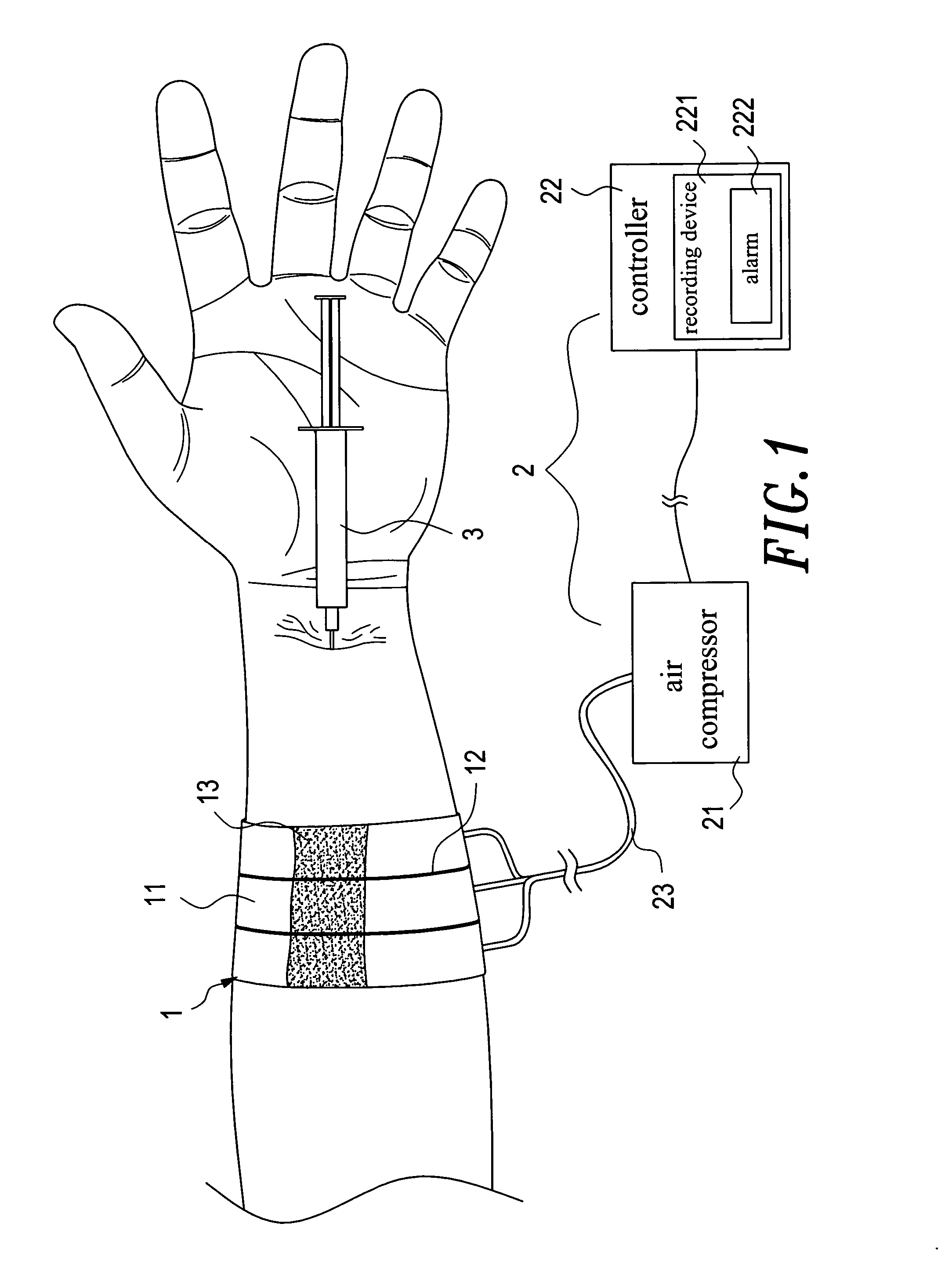
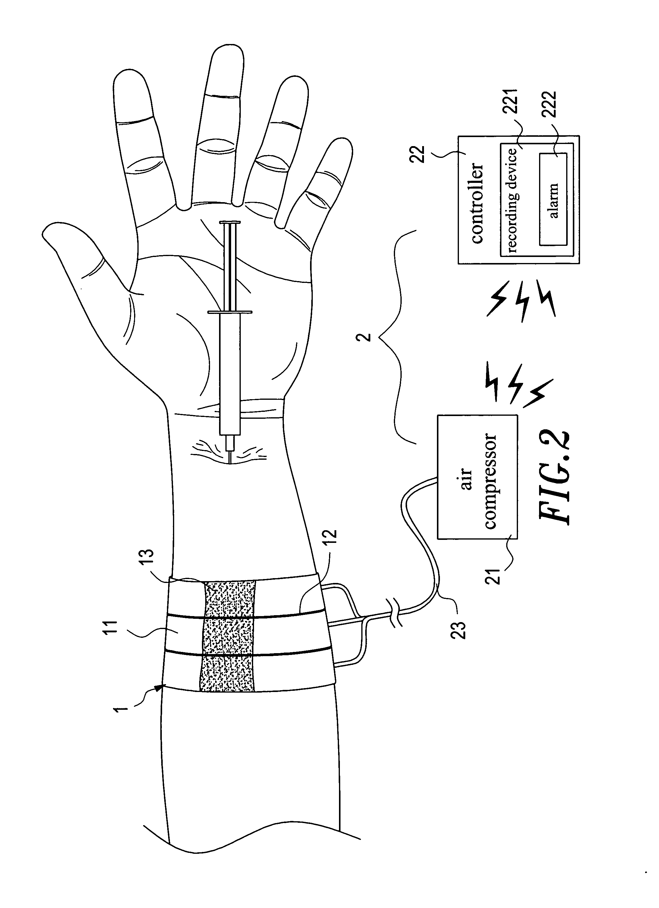
[0004] The present invention provides a safety drawing and injection system that is able to adjust the width of a blood restriction unit thereof in accordance with the size of a patient's forearm. The safety drawing and injecting system is also able to detect a patient's blood pressure and heart rate and the change therein during a treatment.
[0005] Another objective of the present invention is to provide a safety drawing and injection system that makes it unnecessary for a medical person to press the puncture site with her hand. The probability that the medical person becomes infected is thereby reduced.
[0006] Further, the present invention is capable of collating prescriptions, treatment performers, patients, and drugs. The present invention prevents malpractice or errors by ensuring that quick prescription changes are recognized and applied accordingly. In addition, the recorded data can be integrated into the patient's health record and the drug data can be integrated into a hospital management system. The hospital's management efficiency is, thereby, greatly enhanced. The present invention also constitutes a nurse supporting system, because it is capable of forwarding the patient's blood pressure and heart rate to a computer at a nursing station.

Problems solved by technology

However, the conventional method has at least three drawbacks.
Second, the medical person could become infected during the hemostatic procedure.
This is because the medical person has to use her hand to hold the absorbent cotton or haemostatic sponge or gauze while the needle is withdrawn, and the blood from the puncture site could infect the medical person.
It is also possible that the medical person could become infected via needle scratches the medical person's hand.
Third, the conventional method does not detect blood pressure or heart rate during the treatment.

Method used


Image

  • Aspiration and delivery safety system
  • Aspiration and delivery safety system
  • Aspiration and delivery safety system

Examples


first embodiment

[0049] Referring to FIGS. 14 through 28, the present invention further provides a safety intravenous catheter set. As shown in FIGS. 14 and 15, a safety intravenous catheter set of the present invention includes a needle holder 5, a needle cap 6, and a catheter unit 7.

[0050] The needle holder 5 has secured at the front thereof a needle 51 that has formed at a predetermined place thereof an irregular area 511. The irregular area 511 can be constituted by a convex or a concave portion.

[0051] The needle cap 6 comprises an opening 61 bored at the front thereof, a receptive space 62 formed therein, a ring retainer 63 connected to the rear of the opening 61, and a resilient block 64.

[0052] The catheter unit 7 comprises a receptacle 71 and a soft catheter 72. The receptacle 71 receives the needle cap 6. The catheter unit 7 and the needle cap 6 and the needle holder 5 are assembled together, with the needle 51 inserted inside the soft catheter 72. The insertion of the needle 51 presses an...

third embodiment

[0055] Referring to FIGS. 18 and 20, a safety intravenous catheter set of the present invention is shown. The needle cap 6 has a resilient ball 65 installed therein. The rear wall of the needle cap 6 is resilient so as to press the surface of the needle 51. The resilient ball 65 is disposed between one inner wall of the needle cap 6 and the surface of the needle 51. The needle 51 can be withdrawn in a manner similar to the manner mentioned in the aforementioned embodiments. When the needle cap 6 is pulled out from the receptacle 71, the resilient ball 65 expands and tilts the needle cap 6, thereby making the needle 51 point to the lower corner of the receptive space 62. The resilient ball 65 blocks the needle 51 and thereby prevents the needle 51 from protruding. The resilient rear wall of the needle cap 6 retains the irregular area 511 so that the top of the needle 51 cannot be further disconnected from the needle cap 6. The top of the needle 51 is thereby secured inside the needle...

fourth embodiment

[0056] Referring to FIGS. 21 and 23, a safety intravenous catheter set of the present invention is shown. The needle cap 6 has a resilient plate 66 disposed between one inner wall of the needle cap 6 and the surface of the needle 51. The needle holder 5 has a cavity 52 formed at the front thereof. Inside the cavity 52 is installed a filament axle 521 around which a filament 8 is wrapped. The filament 8 has one end thereof connected to the filament axle 521, and the other end thereof connected to the rear of the needle cap 6. The needle 51 can be withdrawn in a manner similar to aforementioned embodiments. When the needle cap 6 is pulled out from the receptacle 71, the resilient plate 66 is released and returns to its neutral position, thereby blocking the needle 51 and preventing the needle 51 from protruding. Alternatively, there is no filament axle disposed inside the cavity 52 and the filament 8 is stored inside the cavity 52, as shown in FIG. 23. The filament 8 has one end there...


PUM


Abstract

An aspiration and delivery safety system that includes a blood restriction unit, an inflating unit, a needle unit, and a puncture site press unit. The blood restriction unit is constituted by a plurality of air bands. The needle unit is a syringe or butterfly needle or blood collector or intravenous catheter or arteriovenous fistula needle. The inflating unit has a controller that monitors a patient's blood pressure and heart rate, and records these data by means of a recording device into which a medical person can also input other medical data. The puncture site press unit has disposed at the bottom thereof a haemostatic element. When applying an intravenous therapy, a needle and a soft catheter are inserted into a patient's body together. The puncture site press device holds the soft catheter during the withdrawal of the needle.

Description

BACKGROUND OF THE INVENTION 1. Field of the Invention [0001] The present invention relates in general to a blood aspiration and drug delivering apparatus, and more particularly, to an aspiration and delivery safety system that is able to prevent medical personal from being infected. [0002] 2. Description of the Prior Art [0003] To withdraw blood or to deliver a drug with a syringe that uses an attached hollow needle, a medical person usually wraps a tourniquet around a patient's forearm at a place above the puncture site in order to make a vein bulge. The medical person can then insert the needle of the syringe into the bulging vein. Or, the medical person can place an intravenous catheter or arteriovenous fistula needle. After that, the medical person removes the tourniquet and further proceeds with blood drawing or drug delivery. When the treatment is finished, the medical person uses absorbent cotton or haemostatic sponge or gauze to press the puncture site and further withdraws ...

Claims


Application Information

Patent Timeline
IPC IPC(8): A61B17/00
CPCA61B5/021A61B5/024A61B5/02405A61B5/1405A61B17/135A61B17/1355A61B5/15003A61B5/150236A61B5/150244A61B5/150389A61B5/150503A61B5/150641A61B5/150648A61B5/15087A61B5/153
Inventor YANG, CHANG-MING
Owner YANG CHANG MING
Learn More