
Wafer cleaning solution for cobalt electroless application

a cobalt electroless and cleaning solution technology, applied in the preparation of detergent mixture compositions, liquid/solution decomposition chemical coatings, inorganic non-surface active detergent compositions, etc., can solve the problems of reducing the reliability of the overall circuit, copper oxide affecting electroless deposition, and affecting the electroless deposition effect of cobalt electroless,

Inactive Publication Date: 2006-08-10
APPLIED MATERIALS INC
View PDF3 Cites 18 Cited by
  • Summary
  • Abstract
  • Description
  • Claims
  • Application Information

AI Technical Summary

Problems solved by technology

However, copper diffuses through substrate and may still electromigrate, thereby requiring a barrier layer between the copper and the substrate.
Copper oxide formation increases the resistance of metal layers (e.g., copper interconnects) and reduces the reliability of the overall circuit.
However, copper oxide detrimentally affects electroless deposition which requires a surface capable of electron transfer for nucleation since oxidized surfaces cannot participate in proper electron transfer and copper oxide may contain contaminants within which interfere with alloy deposition.
Further, the dielectric material may have contaminants thereon that the capping layer deposits to during the electroless plating process.
Deposits of the capping layer on the dielectric material and extensions of the capping layer grown at the edges of the copper lines can cause shorts in the electrical circuit.
Various cleaning solutions that are known and used to clean copper and dielectric materials at other stages during the manufacture of the semiconductor have disadvantages when used prior to depositing the capping layer.
However, the prior cleaning solutions can corrode the copper, etch the copper, roughen the copper surface, and damage the dielectric material.
Additionally, the copper grain boundaries can be decorated by the prior cleaning solutions thereby detrimentally decorating the geometric grain or crystal structure of the copper.
Further, the prior cleaning solutions can go between the barrier layer and the copper or between the barrier layer and the dielectric material and damage these boundaries.

Method used


Image

  • Wafer cleaning solution for cobalt electroless application
  • Wafer cleaning solution for cobalt electroless application
  • Wafer cleaning solution for cobalt electroless application

Examples


Embodiment Construction

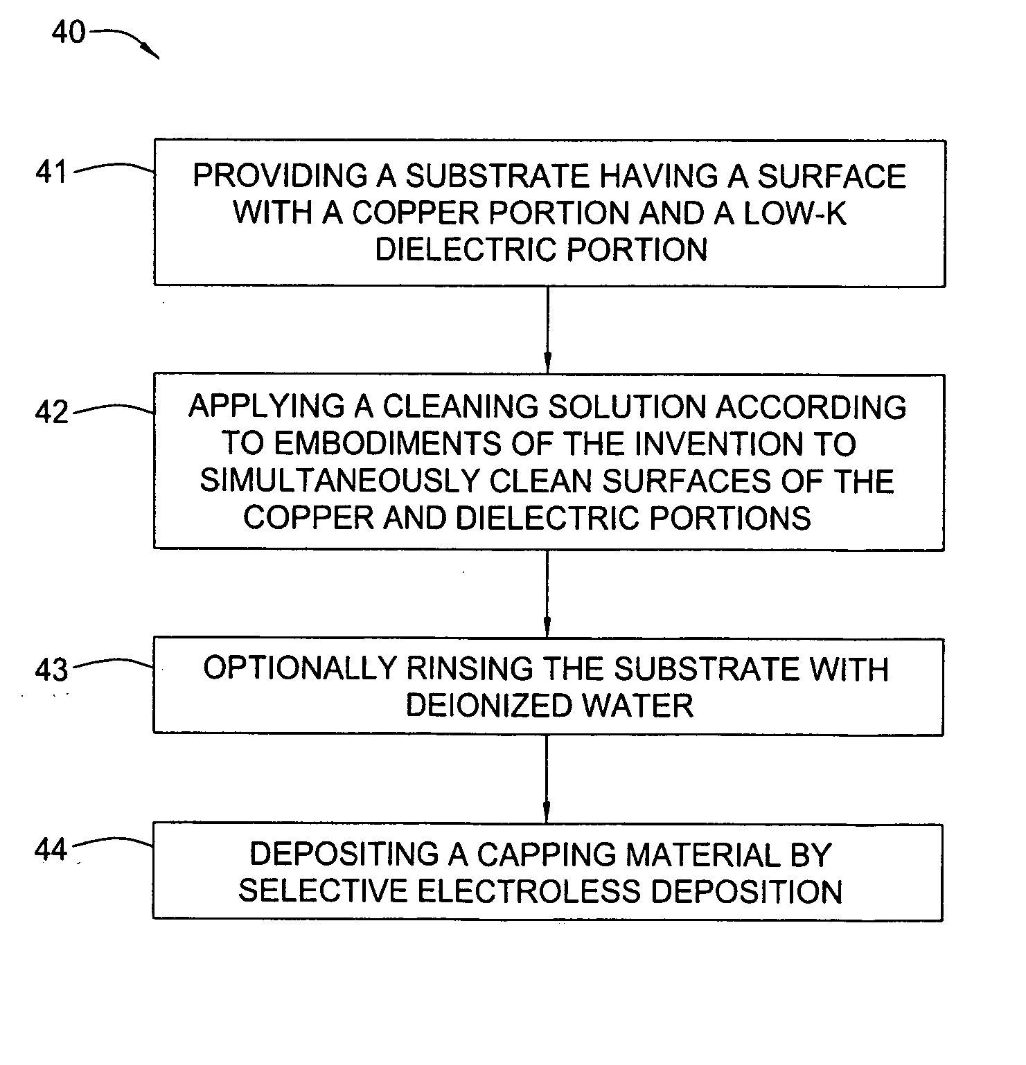
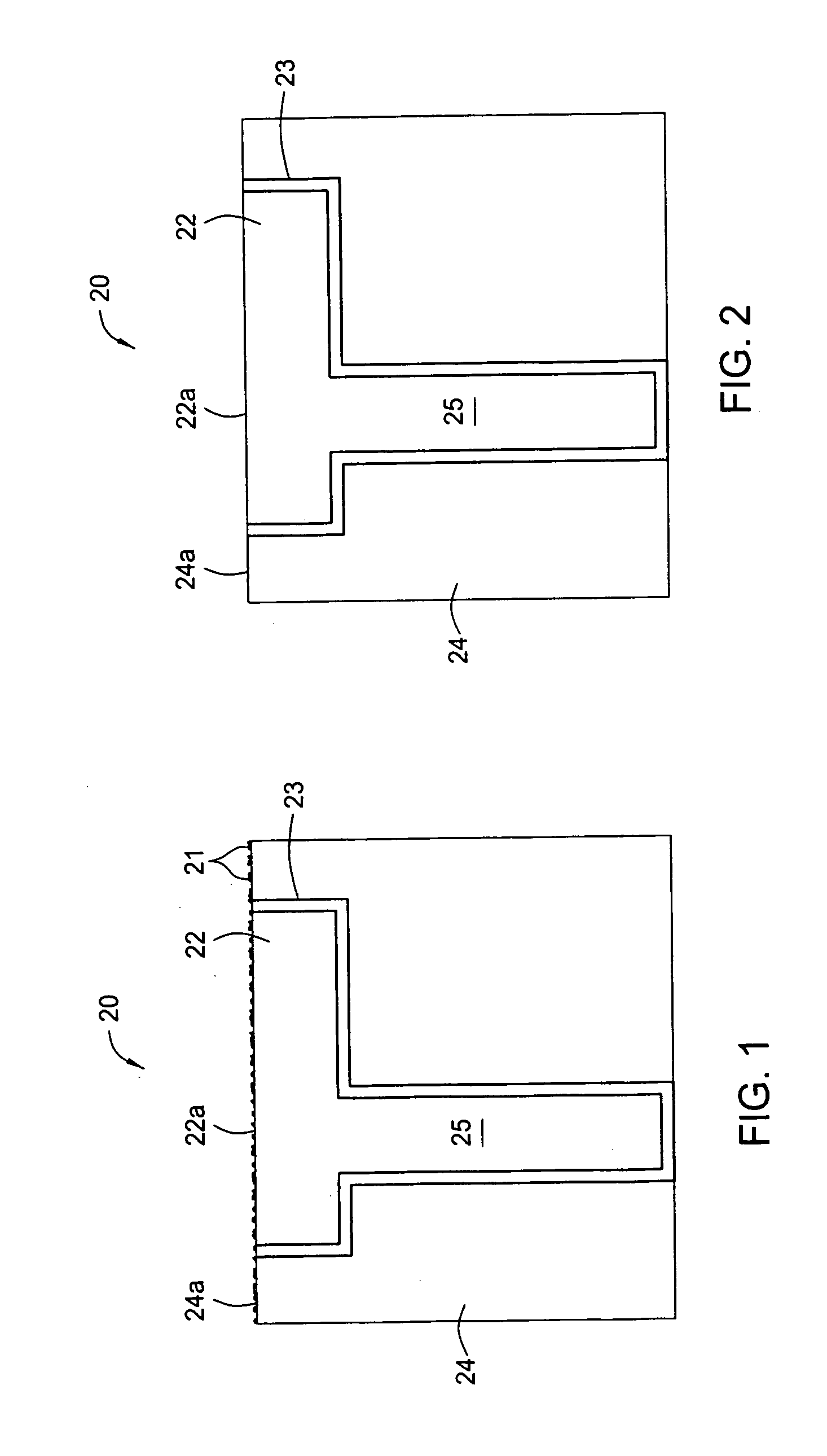
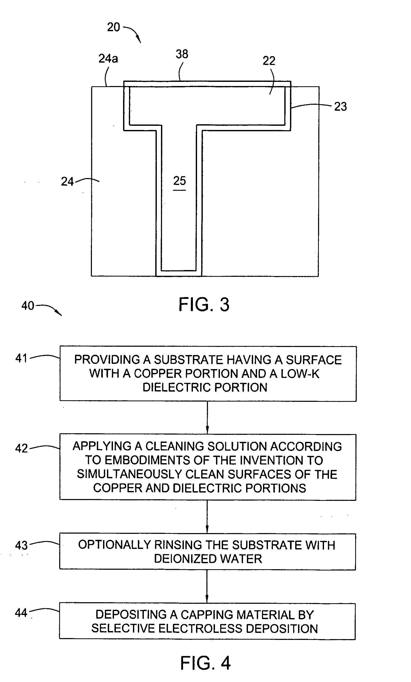
[0016] Embodiments of the invention generally relate to methods and cleaning solutions for removing contaminants from a dielectric material and polished surfaces of copper interconnect structures prior to depositing a capping layer. FIG. 1 shows a schematic cross-section view of an exemplary substrate structure 20 prior to formation of a capping layer over a copper feature. The substrate structure includes a low dielectric constant (low-k) dielectric layer 24 formed over a substrate (not shown), such as a semiconductor substrate or glass substrate, or formed over a substrate as well as other materials formed over the substrate. Examples of low-k materials making up the dielectric layer 24 include Black Diamond™ film, available from Applied Materials, Inc. of Santa Clara, Calif.; CORAL™ film, available from Novellus Systems Inc. of San Jose, Calif., AURORA™ film available from ASM International of Bilthoven, Netherlands; organosilanes or organosiloxanes; spin on dielectrics; carbon d...


PUM

PropertyMeasurementUnit
Fractionaaaaaaaaaa
Fractionaaaaaaaaaa
Fractionaaaaaaaaaa

Abstract

A method and cleaning solution that removes contaminants from a dielectric material and polished surfaces of copper interconnect structures prior to an electroless deposition of a capping layer without substantially adversely affecting the interconnect formed therefrom are disclosed. The cleaning solution includes combinations of a core mixture and sulfuric acid or sulfonic compounds such as sulfonic acids that include methanesulfonic acid. In one embodiment, the core mixture includes a citric acid solution and a pH adjuster such as tetra-methyl ammonium hydroxide or ammonia. One embodiment of the method includes providing a planarized substrate, applying the cleaning solution to the substrate to simultaneously clean at least one metal feature and a dielectric material of the substrate, and depositing the metal capping layer selectively on the at least one metal feature using electroless deposition.

Description

CROSS-REFERENCE TO RELATED APPLICATIONS [0001] This application claims benefit of U.S. provisional patent application Ser. No. 60 / 536,958, filed Jan. 16, 2004, which is herein incorporated by reference.BACKGROUND OF THE INVENTION [0002] 1. Field of the Invention [0003] Embodiments of the invention generally relate to a cleaning solution for use during the fabrication of semiconductor devices. More particularly, the invention relates to cleaning solutions and methods for using the cleaning solutions prior to depositing metal alloy capping layers over conductive layers in electronic devices. [0004] 2. Description of the Related Art [0005] Recent improvements in circuitry of ultra-large scale integration (ULSI) on substrates indicate that future generations of semiconductor devices will require multi-level metallization with smaller geometric features. The multilevel interconnects that lie at the heart of this technology require planarization of interconnect features formed in high asp...

Claims


Application Information

Patent Timeline
IPC IPC(8): B08B6/00H01L21/4763C25F1/00
CPCC11D7/06C11D7/08C11D7/265C11D11/0047C23F1/18C23G1/103H01L21/02074H01L21/76826H01L21/76849H01L21/76877H01L21/76883C23C18/1844C11D2111/22
Inventor EMAMI, RAMINWEIDMAN, TIMOTHYLOPATIN, SERGEYFANG, HONGBINSHANMUGASUNDRAM, ARULKUMAR
Owner APPLIED MATERIALS INC
Learn More