
Ion gun deposition and alignment for liquid-crystal applications

a technology of liquid crystals and aligned atomic structures, applied in the direction of vacuum evaporation coatings, instruments, transportation and packaging, etc., can solve the problems of reducing the process yield, affecting the quality of the rubbing process, and the choice of materials suitable for the rubbing process is limited, so as to reduce the potential contamination of the surface, simple and cost-effective, and easy processing

Inactive Publication Date: 2006-07-13
GLOBALFOUNDRIES INC
View PDF16 Cites 5 Cited by
  • Summary
  • Abstract
  • Description
  • Claims
  • Application Information

AI Technical Summary

Benefits of technology

[0020] The method by which these films are prepared is a dry deposition and alignment technique, which reduces the need for pre- and post-wet processing. The present method is also a non-contact deposition and alignment technique, which reduces any potential contamination of the surface by extraneous debris, such as those commonly encountered in the contact rubbing techniques of the prior art.
[0021] Accordingly, the present invention provides a simple and cost effective method of forming easily processed aligned films on which liquid crystals can be aligned for use in wide viewing angle liquid-crystal displays.

Problems solved by technology

For example, because the rubbing method is a contact technique, debris can be generated during the rubbing process resulting in a low process yield.
Also, as the roller or brush rubs the surface of the display, electrostatic charges can build up which may discharge through the thin film transistors (TFT) resulting in a lowering of the process yield.
Thus, choice of materials that are suitable for use in the rubbing process is limited.
While a wide variety of surfaces were found to be suitable for alignment by an ion beam technique, the reference does not teach the deposition of the alignment layer and the alignment of the layer in a single step.
Consequently, the deposition of an alignment layer and subsequent alignment of the alignment layer in separate process steps introduces additional costs into the manufacturing process.

Method used


Image

  • Ion gun deposition and alignment for liquid-crystal applications
  • Ion gun deposition and alignment for liquid-crystal applications
  • Ion gun deposition and alignment for liquid-crystal applications

Examples


second embodiment

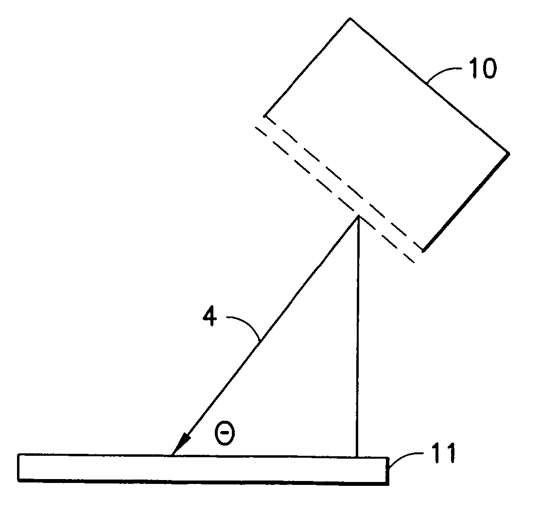
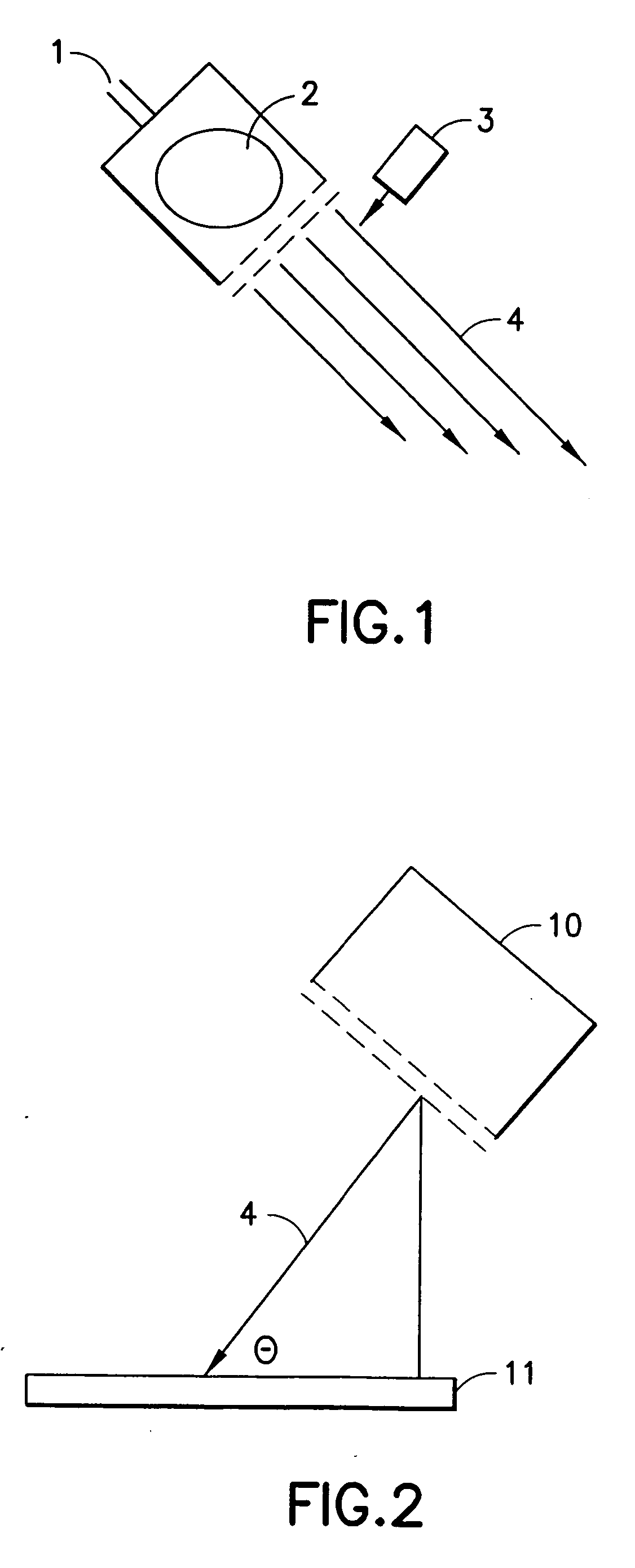
[0045] In a second embodiment, one or more ion sources can be held in a fixed position while the substrates to be coated with the aligned amorphous film are moved beneath the ion sources. In this embodiment, substrates larger than the ion sources can be processed.

third embodiment

[0046] In a third embodiment, the substrate or substrates to the processed are held stationary whereas the ion sources are moved relative to the substrates. Once again in this embodiment, the movement of the ion sources allows for the processing of substrates that are larger than the ion sources.

fourth embodiment

[0047] In the apparatus either the substrates or the ion sources are capable of movement, but the angle of incidence of the ion sources relative to one another can be the same or different. Thus, the angle of incidence of the ion sources relative to one another can be fixed for the duration of the process or it can be variable, i.e., changed during the processing of the substrates.


PUM

PropertyMeasurementUnit
Angleaaaaaaaaaa
Energyaaaaaaaaaa
Energyaaaaaaaaaa

Abstract

An apparatus for depositing and aligning an amorphous film in a single step, a method of forming an aligned film on a substrate in a single step by combining the deposition and alignment of an alignment layer into a single-step using ion beam processing and an amorphous film having an aligned atomic structure prepared by a method in which an aligned film is deposited and aligned in a single step are provided. The film is deposited and aligned in a single step by bombarding a substrate with an ion beam at a designated incident angle to simultaneously (a) deposit the film onto the substrate and (b) arrange an atomic structure of the film in at least one predetermined aligned direction.

Description

APPLICATIONS [0001] This application is a Continuation-In-Part of and claims priority from U.S. application Ser. No. 09 / 608,798, filed on Jun. 30, 2000.BACKGROUND OF THE INVENTION [0002] 1. FIELD OF THE INVENTION [0003] The present invention relates to an amorphous film having an aligned atomic structure and an apparatus for making such an amorphous aligned film. More particularly, the present invention relates to an amorphous film having an aligned atomic structure prepared by a method in which an aligned film is deposited and aligned in a single step and to an apparatus for depositing and aligning such as an amorphous film in a single step. [0004] 2. DESCRIPTION OF THE PRIOR ART [0005] The alignment of liquid crystal molecules on a surface is one of the critical steps in the manufacturing of a liquid crystal display. The industry-wide method for producing such alignment is through the mechanical rubbing of a polyimide surface. This method requires a physical contact between a roll...

Claims


Application Information

Patent Timeline
IPC IPC(8): C23C16/00G02F1/1333C23C14/06C23C14/22C23C14/34G02F1/1337
CPCC23C14/0605C23C14/221C23C14/225Y10T428/30C23C14/5833G02F1/133734G02F1/13378C23C14/3442G02F1/1333
Inventor CALLEGARI, ALESSANDRO CESARECHAUDHARI, PRAVEENDOYLE, JAMES PATRICKGALLIGAN, EILEEN ANNKATO, YOSHIMINELACEY, JAMES ANDREWLIEN, SHUI-CHIH ALANLU, MINHUANAKANO, HIROKIODAHARA, SHUICHI
Owner GLOBALFOUNDRIES INC
Learn More