
Low refractive index fluoropolymer coating compositions for use in antireflective polymer films

a technology of anti-reflection polymer and coating composition, which is applied in the field of anti-reflection films, can solve the problems of reducing the surface energy of the coating layer, reducing the interfacial adhesion of the fluoropolymer layer to other polymer or substrate layers to which the layer is attached,

Active Publication Date: 2006-07-06
3M INNOVATIVE PROPERTIES CO
View PDF56 Cites 82 Cited by
  • Summary
  • Abstract
  • Description
  • Claims
  • Application Information

AI Technical Summary

Benefits of technology

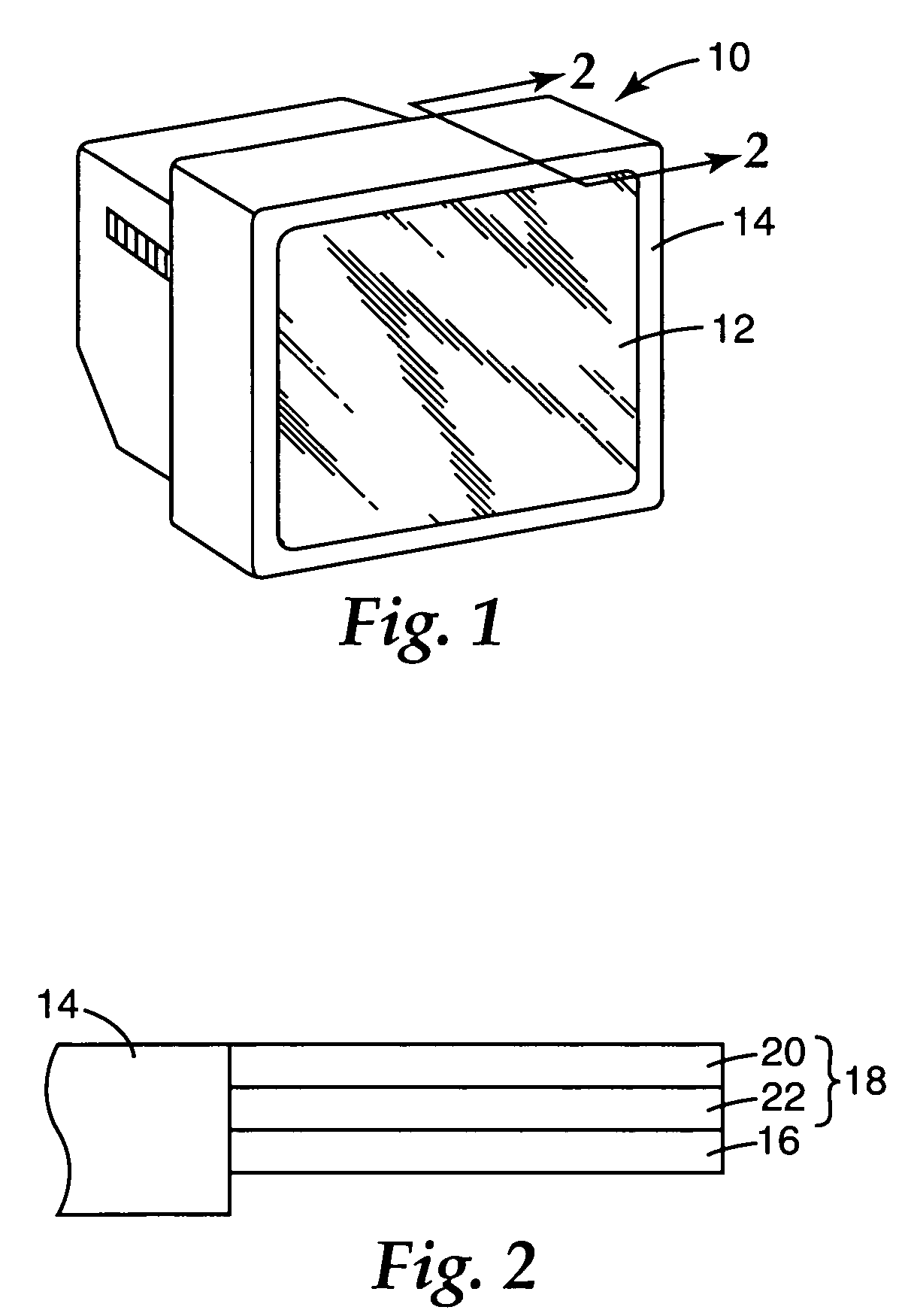
[0007] The present invention provides an economic and durable low refractive index fluoropolymer composition for use as a low refractive index film layer in an antireflective film for an optical display. The low refractive index composition forms layers having strong interfacial adhesion to a high index refractive layer and / or a substrate material.
[0009] The term “reactive fluoropolymer”, or “functional fluoropolymer” will be understood to include fluoropolymers, copolymers (e.g. polymers using two or more different monomers), oligomers and combinations thereof, which contain a reactive functionality such as a halogen-containing cure site monomer or halogen-containing endgroup and / or a sufficient level of unsaturation. This functionality allows for further reactivity between the other components of the coating mixture to facilitate network formation during cure and improve further the durability of the cured coating.
[0010] Further, the mechanical strength and scratch resistance of any of above low refractive index compositions can be enhanced by the addition of surface functionalized nanoparticles or by a sol gel precursor into the fluoropolymer compositions.
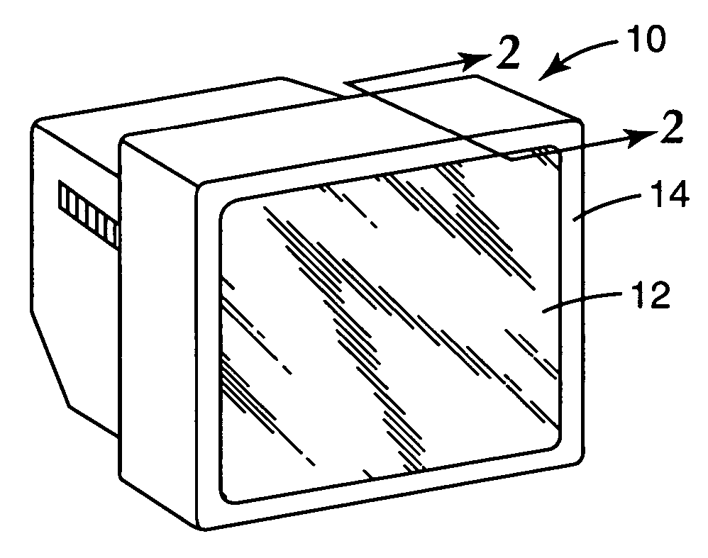
[0011] The present invention also provides an article having an optical display that is formed by introducing the antireflection film having a layer of the above low refractive index compositions to an optical substrate. The resultant optical device has an outer coating layer that is easy to clean, durable, and has low surface energy.

Problems solved by technology

However, increasing the fluorine content of fluoropolymer coating layers can decrease the surface energy of the coating layers, which in turn can reduce the interfacial adhesion of the fluoropolymer layer to other polymer or substrate layers to which the layer is coupled.

Method used


Image

  • Low refractive index fluoropolymer coating compositions for use in antireflective polymer films
  • Low refractive index fluoropolymer coating compositions for use in antireflective polymer films
  • Low refractive index fluoropolymer coating compositions for use in antireflective polymer films

Examples


examples

[0091] The following paragraphs illustrate, via a specific set of example reactions and experimental methodologies, the improvements of each of the component steps for forming the low refractive index composition of the present invention. The paragraphs detail test methods, ingredients, and experimental tests done to confirm the improvements of each component step.

A. Test Methods

1. Peel Strength

[0092] A peel strength was used to determine interfacial adhesion. To facilitate testing of the adhesion between the layers via a T-peel test, a thick film (20 mil (0.51 mm)) of THV 220 or FC 2145 was laminated onto the side of the films with the fluoropolymer coating in order to gain enough thickness for peel measurement. In some cases, a slight force was applied to the laminated sheet to keep a good surface contact. A strip of PTFE fiber sheet was inserted about 0.25 inch (0.64 mm) along the short edge of the 2 inch×3 inch (5.08 cm×7.62 cm) laminated sheet between the substrate surface...

example set 1

Interfacial Adhesion Improvement Between Fluoropolymers and Substrates

[0131] Dyneon™ Fluoroplastic THV™ 220, Dyneon™ fluoroelastomer FC-2145 or brominated fluoroelastomer E-15742 were each dissolved individually in containers with either MEK or ethyl acetate at 5 weight percent by shaking at room temperature. The prepared fluoropolymer solutions were then combined with an aminosilane / methanol solution, such as 3-aminopropyltrimethoxysilane (or A1106 in methanol) in various ratios. The solids were diluted to 3% solids in Methyl ethyl ketone and coated on the substrate with a #3 Meyer Rod. The mixed fluoropolymer / aminosilane solutions were applied to S1 or S2. This gave a calculated dry coating thickness of approximately 100 nm. The coated films were dried briefly, then subjected to heating at 100-120° C. for 10 minutes.

[0132] Subsequently the films were further subjected to UV irradiation by H-bulb or by a 254 nanometer (nm) lamp, or simply subjected to heat, or thermal and UV comb...

example set 2

Photocrosslinking / Photografting of Fluoropolymers

[0134] The above prepared fluoropolymer solutions in Example 1 were combined with one or more crosslinkers as shown in Table 7. The various compositions of coating solutions were allowed to sit in an airtight container. The solutions were then applied as a wet film to (S1) or (S2) in the same manner as described for Example Set 1. The coated films were dried in an oven at 100-120° C. for 10 minutes.

[0135] Subsequently the films were subjected to UV (H-bulb) irradiation by 3 passes at the speed of 35 feet per minute. Alternatively, the films were subjected to UV irradiation from a 254-nanometer (nm) bulb using a similar approach. The resulting films were carefully removed from the coating substrates and cut into smaller pieces and placed into vials containing MEK solvent. The vials were visually observed to determine whether the film was soluble or insoluble in the MEK solvent. Solutions classified as “insoluble” indicated that the f...


PUM

PropertyMeasurementUnit
refractive indexaaaaaaaaaa

Abstract

An economic, optically transmissive, stain and ink repellent, durable low refractive index fluoropolymer composition for use in an antireflection film or coupled to an optical display. In one aspect of the invention, the composition is formed from the reaction product of a fluoropolymer or reactive fluoropolymer, an amino silane ester coupling agent or ester equivalent, a multi-olefinic crosslinker, and optional surface modified inorganic particles or sol gel precursors.

Description

TECHNICAL FIELD AND INDUSTRIAL APPLICABILITY OF THE INVENTION [0001] The present invention relates to antireflective films and more specifically to low refractive index fluoropolymer coating compositions for use in antireflection polymer films. BACKGROUND OF THE INVENTION [0002] Antireflective polymer films (“AR films”) are becoming increasingly important in the display industry. New applications are being developed for low reflective films applied to substrates of articles used in the computer, television, appliance, mobile phone, aerospace and automotive industries. [0003] AR films are typically constructed by alternating high and low refractive index (“RI”) polymer layers in order to minimize the amount of light that is reflected from the optical display surface. Desirable product features in AR films for use on optical goods are a low percentage of reflected light (e.g. 1.5% or lower) and durability to scratches and abrasions. These features are obtained in AR constructions by m...

Claims


Application Information

Patent Timeline
Patent Type & Authority Applications(United States)
IPC IPC(8): B32B27/00B05D5/06B05D3/02C07C61/08
CPCY10T428/24942G02B1/111Y10T428/3154Y10T428/31663G02B1/10G02B1/11B82Y40/00
Inventor JING, NAIYONGCAO, CHUNTAOFUKUSHI, TATSUOTATGE, TIMOTHY J.COGGIO, WILLIAM D.WALKER, CHRISTOPHER B.KLUN, THOMAS P.SCHULTZ, WILLIAM J.QIU, ZAI-MING
Owner 3M INNOVATIVE PROPERTIES CO
Learn More