
Tunneler with an expandable attachment mechanism

a technology of a tunneller, which is applied in the field of tunnellers with an expandable attachment mechanism, can solve the problems of increased infection risk, increased risk of infection, damage to the lumen and the distal tip of the catheter, etc., and achieves the effects of reducing the pressure on the inner lumen surface of the catheter, minimizing abrasion, and improving the connection to the catheter

Active Publication Date: 2006-06-22
CR BARD INC
View PDF57 Cites 79 Cited by
  • Summary
  • Abstract
  • Description
  • Claims
  • Application Information

AI Technical Summary

Benefits of technology

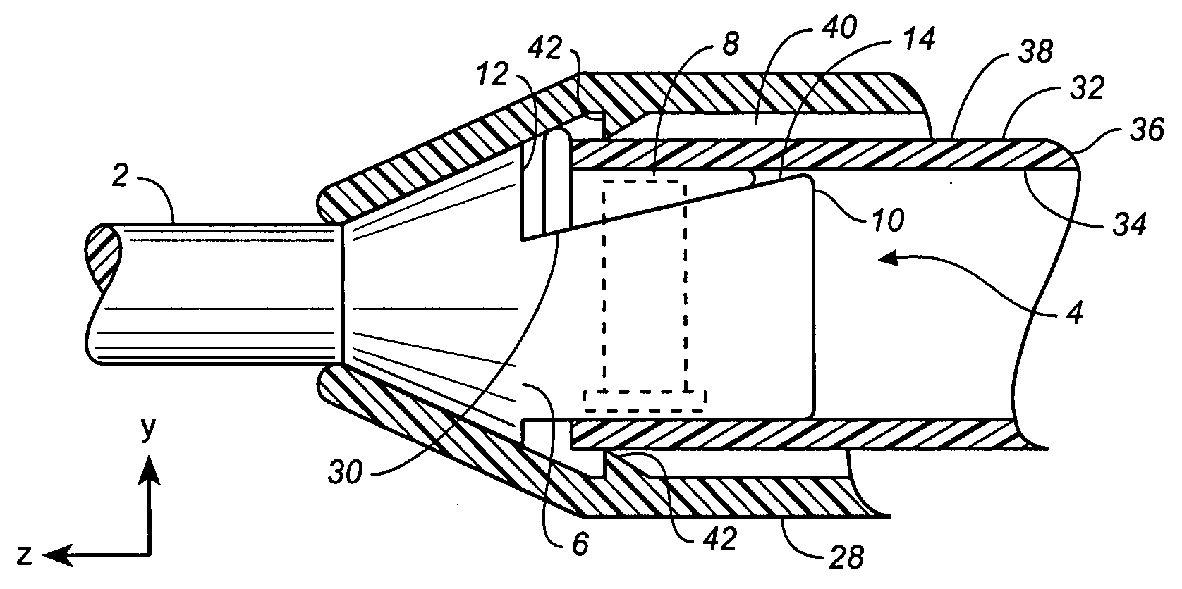
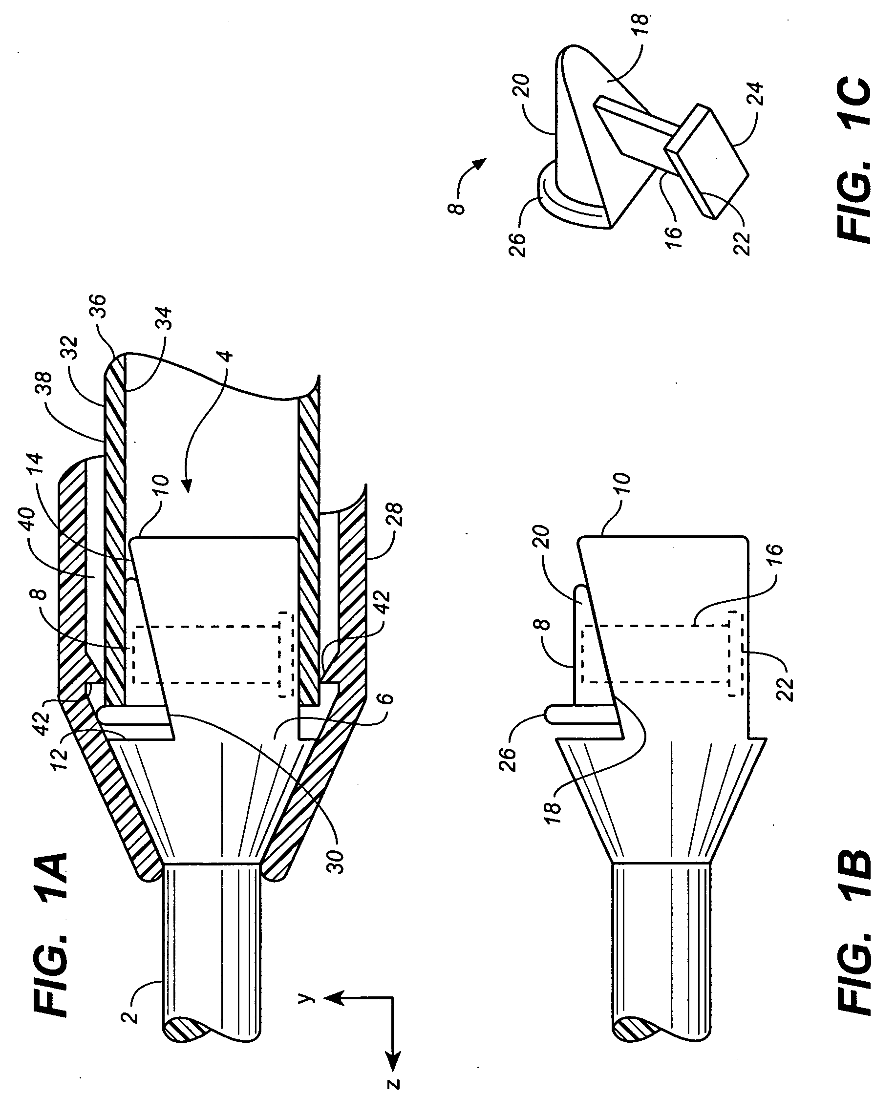
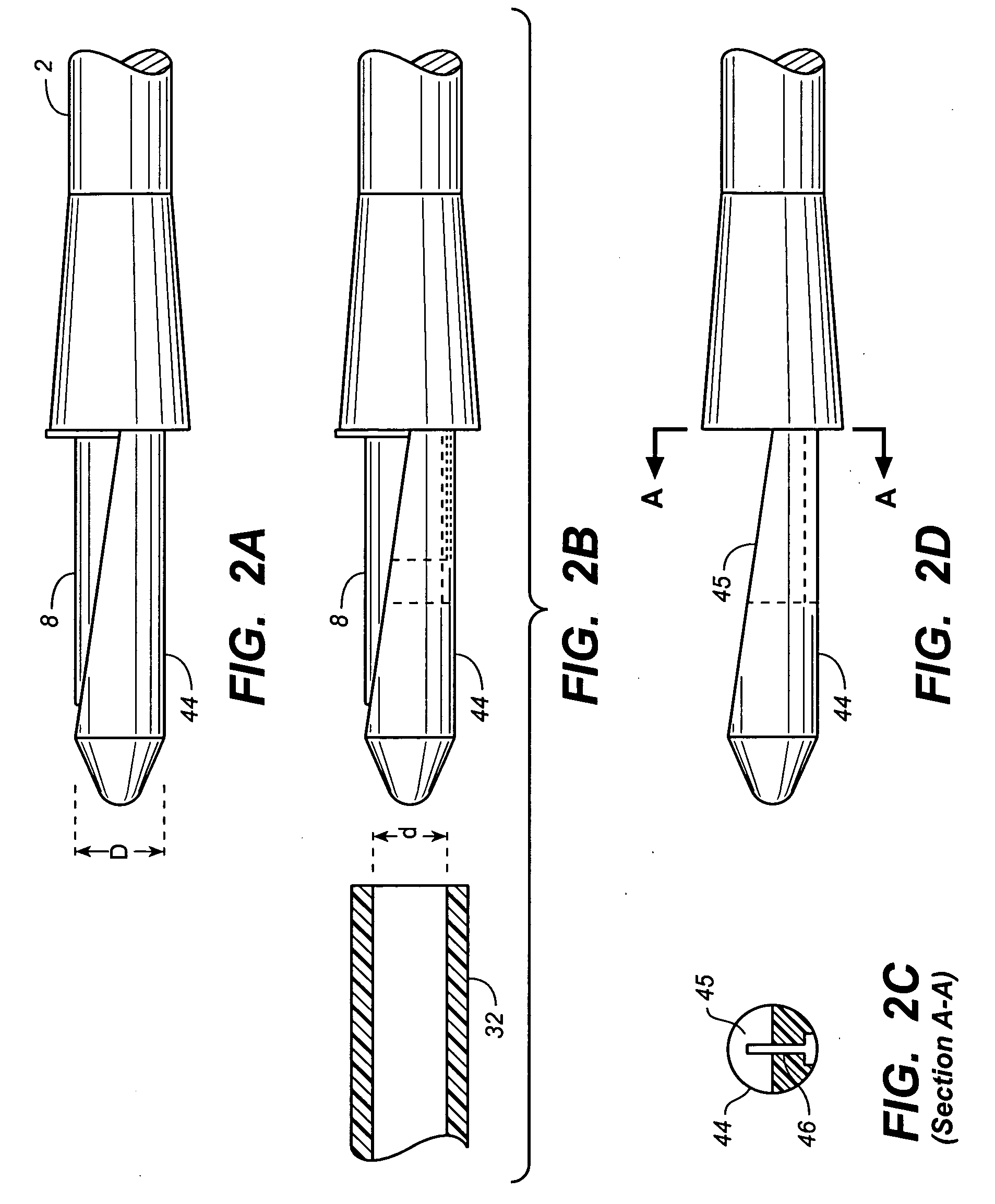
[0010] Accordingly, described herein is a tunneler including an expandable attachment mechanism for securing a catheter onto the proximal end of a tunneler. In one aspect of the invention, the tunneler comprises an extension protruding from the proximal end thereof for insertion into the lumen of a catheter. The, extension includes an expansion mechanism that allows it to expand laterally and / or radially inside the lumen of the catheter. The expansion mechanism may be further configured to interlock with an oversleeve, such that when the oversleeve is slid over the portion of the catheter positioned around the proximal end protrusion, the expansion mechanism expands and traps the catheter between the expansion mechanism and the inner wall of the oversleeve. Because a lateral force perpendicular to the axis of the tunneler is applied by the expansion mechanism from inside the lumen, grinding of the catheter's exterior surface by the oversleeve is minimized.
[0011] The tunneler may be further configured such that withdrawal of the oversleeve displaces the expansion mechanism and release the pressure on the inner wall of the catheter. Once the expansion mechanism has contracted, the catheter may then be easily removed. Furthermore, ribs, grooves or other surface profiles may be provided on the outer surface of expansion mechanism and / or the inner surface of the oversleeve to enhance the tunneler's ability to retain the catheter on the expansion mechanism.
[0012] In one variation, the tunneler comprises a protrusion extending from the proximal end of the tunneler body for insertion into the lumen of a catheter. The protrusion further comprises a sliding cam forming an expansion mechanism on the protrusion. As the oversleeve of the tunneler engages the sliding cam, the overall cross-section of the protrusion expands, trapping the catheter wall between the sliding cam and the inner wall of the oversleeve and securing the catheter to the proximal end of the tunneler. As the oversleeve is withdrawn, it forces the displacement of the sliding cam toward the distal end of the catheter, thereby decreasing the overall cross-section of the protrusion and releasing the compression pressure on the catheter. The catheter may then be easily removed form the protrusion.
[0014] In yet another variation, an expandable elastomeric ring is positioned at the proximal portion of the tunneler for attaching a catheter onto the tunneler. With the proximal portion of the tunneler inserted inside the catheter, the elastomeric ring is expanded to engage the inner wall of the catheter and secure the catheter on the proximal end of the tunneler. To release the catheter, the elastomeric ring is allowed to contract and thus relieving the pressure on the catheter's inner lumen surface.
[0015] The expandable attachment mechanism design implemented at the proximal end of the tunneler may provide various advantages, including, but not limited to: 1) minimizing the abrasion to the tip and the outer surface of the catheter due to placement and removal of the oversleeve; 2) providing an improved connection to the catheter because the compression force is applied directly in the radial direction from the inner catheter lumen; 3) providing some accommodation to variation in lumen sizes as the tunneler / catheter interface is expandable; 4) facilitating the placement and removal of the catheter onto and from the tunneler due to the expansion mechanism being in a contracted state during each procedure.

Problems solved by technology

However, a common problem associated with implanted catheters is the increased risk of infection due to the establishment of this artificial path into the patient's body.
The risk of infection increases the longer the catheter remains implanted.
One of the disadvantages of the current tunneling devices is that attachment and removal of the barbed end of the tunneler from the lumen of the catheter often results in damage to the lumen and the distal tip of the catheter.
Typically, the barb is much larger than the diameter of the catheter lumen and thus forces the tip of the catheter to expand radially and makes the tip prone to damage.
Moreover, with respect to the typical use of an oversleeve, the axial motion along the length of the tunneler, which pushes the oversleeve onto the expanded catheter over the barb or pulls the oversleeve off the expanded catheter over the barb, may cause significant abrasion on the exterior of the catheter body.
In addition, such lateral grinding of the oversleeve onto the catheter over the barb may cause tearing of the catheter body.

Method used


Image

  • Tunneler with an expandable attachment mechanism
  • Tunneler with an expandable attachment mechanism
  • Tunneler with an expandable attachment mechanism

Examples


Embodiment Construction

[0062] The following detailed description should be read with reference to the drawings, in which like elements in different drawings may be identically numbered. The drawings, which are not necessarily to scale, depict selected preferred embodiments and are not intended to limit the scope of the invention. The detailed description illustrates by way of example, not by way of limitation, the principles of the invention. This description will clearly enable one skilled in the art to make and use the invention, and describes several embodiments, adaptations, variations, alternatives and uses of the invention, including what is presently believed to be the best mode of carrying out the invention.

[0063] Before describing the present invention, it is to be understood that unless otherwise indicated this invention need not be limited to applications in humans. As one of ordinary skill in the art would appreciate, variations of the invention may be applied to other mammals as well. Moreov...


PUM


Abstract

A tissue tunneler including an expandable attachment mechanism for securing a catheter. In one variation, the tissue tunneler comprises an elongate tunneler with a protrusion extending from the proximal end of the tunneler. An expansion mechanism is provided on the protrusion for insertion into the catheter. An oversleeve slidably disposed over the elongated tunneler may be provided to engage the expansion mechanism and trap the catheter between the oversleeve and the expansion mechanism. In another variation, the expansion mechanism may comprise of an expandable O-ring configured to engage an inner surface within a catheter.

Description

CROSS-REFERENCE TO RELATED APPLICATIONS [0001] Not applicable. STATEMENT REGARDING FEDERALLY SPONSORED RESEARCH OR DEVELOPMENT [0002] Not applicable. REFERENCE TO A COMPACT DISK APPENDIX [0003] Not applicable. BACKGROUND OF THE INVENTION [0004] In various medical applications an implanted catheter is needed to access a patient's circulatory system. The implanted catheter may be utilized, for example, for delivery of medication / fluids or retrieval / sampling of blood. For example, it may be desirable to establish a central line (i.e., access to a large vein) for infusion of medications, chemotherapy drugs, antibiotics, anti-nausea medications, blood products, nutrients or fluids. Implanted catheters are also used in dialysis, apheresis, and other applications requiring diversion of a part of the blood flow in the circulatory system for processing or filtering. However, a common problem associated with implanted catheters is the increased risk of infection due to the establishment of th...

Claims


Application Information

Patent Timeline
IPC IPC(8): A61M39/10
CPCA61B17/3415A61B2017/320044A61B2017/320056A61M39/12
Inventor ROME, GUY T.BARRON, WILLIAM R.
Owner CR BARD INC
Learn More