Eureka AIR delivers breakthrough ideas for toughest innovation challenges, trusted by R&D personnel around the world.

Thermal attach and detach methods and system for surface-mounted components

Inactive Publication Date: 2006-06-22
HEETRONIX
View PDF5 Cites 9 Cited by
  • Summary
  • Abstract
  • Description
  • Claims
  • Application Information

AI Technical Summary

Benefits of technology

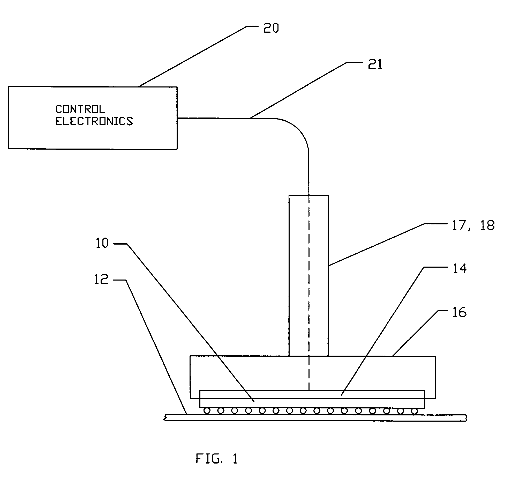
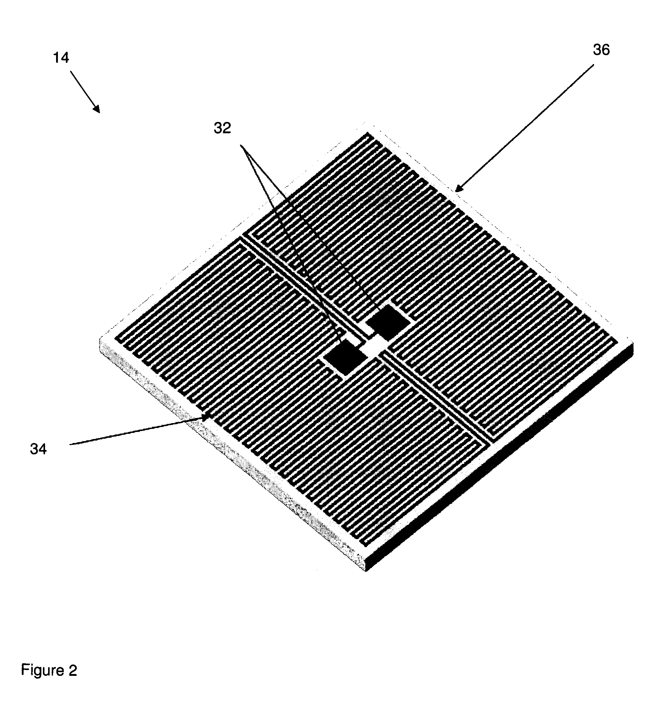
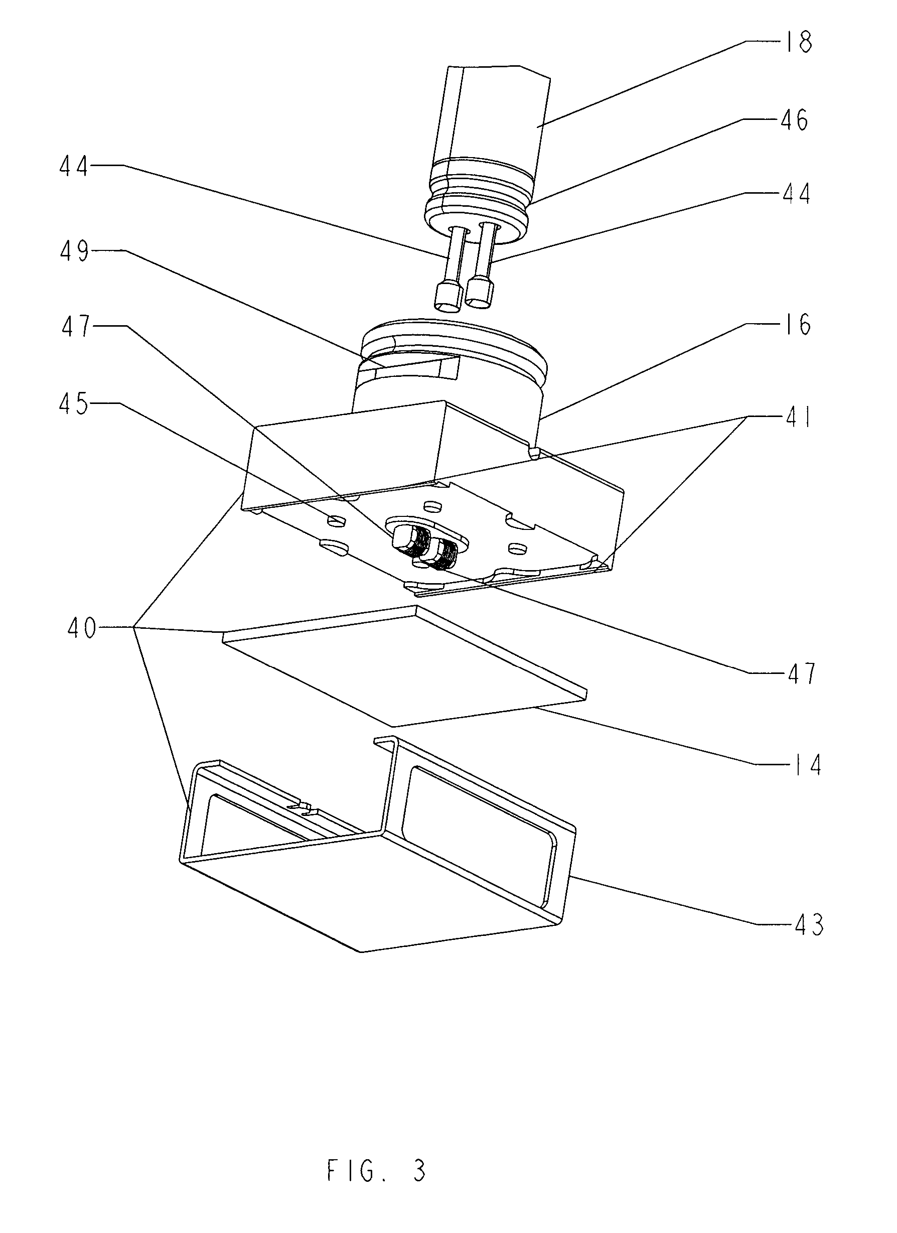
[0030] The present method employs a “planar-heater” heating element, which generates heat in response to an electrical current. The heater's resistance varies with its temperature, and the resistance is read to determine heater temperature and to measure SMD temperature. Means of gripping an SMD are provided such that the SMD's I / O contacts are heated by thermal conduction from the planar-heater through and / or along the side-walls of the SMD. An electrical current is provided to the planar-heater such that heat sufficient to solder / desolder the I / O contacts to or from a PCB is generated. The present method enables the gripping, heating and resistance monitoring and SMD temperature measurements to occur simultaneously.

Problems solved by technology

The density of SMCs, such as SMDs, mounted on a substrate such as a printed circuit board (PCB) is increasing, as is the complexity of the circuitry within the SMDs.
This is particularly true for Multi-Chip Modules (MCMs), which use higher melting temperature solder or epoxy processes for assembly and can be irreversibly damaged by subsequent exposure to temperatures approaching those at which the original MCM was assembled.
However, this is no longer true in many cases.
Since the gas is not a very efficient heat transfer mechanism, it must be well above the melting temperature of the solder to actually melt the solder.
The high temperature of the gas stream is a risk to the SMC itself as well as to adjacent SMCs and the PCB.
The temperature of an exiting gas stream as it impinges on the component cannot be very accurately controlled since there is no means for measurement at the SMC / heater interface.
Thus, it is not possible to accurately control desolder, solder and resolder processes or to accurately replicate the original reflow oven attachment sequence.
It is difficult to confine the heating to only the area of the target SMC.
However, these require customization of the rework tooling for each SMC size, and hence add to the overall rework cost.
The gas jet method cannot be applied exclusively to the top of the SMC.
The high temperature required due to the relatively low heat transfer efficiency of the gas causes the resulting exposure times to be longer than for direct heating of the solder, thus posing a risk to the SMC and its internal components.
There are also drawbacks associated with soldering irons.
The temperature to which the SMC is heated is very difficult to control precisely because: (1) the soldering iron tip temperature is often inferred from a temperature measurement taken elsewhere on the soldering iron, and (2) measuring the temperature in this way is subject to further inaccuracy due to changes in the thermal contact between the soldering iron and the thermocouple and to the change of the thermocouple's temperature response over time.
Unintentional excessive reflow of solder may occur, possibly damaging the components inside the SMC, or between pads on the PCB.
The large thermal mass of the soldering iron precludes the implementation of temperature ramps during solder / desolder operations.
Since many current PCB assemblies have components on both sides, the bottom-side heat creates additional risk of component damage.
However, as noted above, gases are relatively inefficient heat transfer mediums; as such, the gas temperature must be considerably higher than the target PCB temperature.
This inefficiency may also result in the need for an extended exposure time which may risk damage to the PCB and its components.
Gas temperatures can also be difficult to control.
Using IR radiating elements to heat a PCB can also be problematic.
Due to wide variances in the materials used for PCBs, and the reflectivity of PCB surface coatings, uniform heating of the PCB—and precise control of temperature—can be difficult.

Method used


Image

  • Thermal attach and detach methods and system for surface-mounted components
  • Thermal attach and detach methods and system for surface-mounted components
  • Thermal attach and detach methods and system for surface-mounted components

Examples


Embodiment Construction

[0056] The present invention enables SMCs to be simultaneously held, heated, positioned, thermally attached to a substrate or thermally detached and removed from a substrate, with the SMC's temperature being measured at all times. Substrates and PCBs themselves can also be heated by the present invention, to remove moisture before and minimize thermal stress during the attachment or removal of a component from the PCB, or to effect the component removal itself. A system in accordance with the invention can be hand-held or robotically deployed. It can precisely position a planar-heater on an SMC of any size, and precisely position an SMC on a substrate or grasp and pull an SMC that is to be removed from a substrate.

[0057] An illustration of a basic system per the present invention is shown in FIG. 1. An SMC 10 is to be attached to or detached from a substrate 12. Soldering and desoldering of SMDs from PCBs is used to explain the basic system in the following description.

[0058] The ...


PUM

PropertyMeasurementUnit
Temperatureaaaaaaaaaa
Forceaaaaaaaaaa
Magnetic fieldaaaaaaaaaa

Abstract

A thermal attach and detach method and system for surface-mounted components (SMCs) employs a planar-heater which generates heat in response to an electrical current. The heater's resistance varies with its temperature, and the resistance is read to determine heater and SMC temperature. A means of gripping an SMC is provided such that the device's I / O contacts are heated by thermal conduction from the planar-heater through and / or along the SMC's side-walls. An electrical current is provided to the planar-heater such that heat sufficient to attach / detach the I / O contacts to or from a PCB is generated. The method enables the gripping, heating, resistance monitoring and SMC temperature measuring to occur simultaneously. Several means of gripping an SMC are described, including vacuum, mechanical, adhesive and magnetic. A method which employs a heating element to heat a substrate on which SMCs may be mounted is also described.

Description

[0001] This application claims the benefit of provisional patent application No. 60 / 631,913 to Durston et al., filed Nov. 29, 2004, and provisional patent application No. 60 / 684,539 to Durston et al., filed May 24, 2005.BACKGROUND OF THE INVENTION [0002] 1. Field of the Invention [0003] This invention relates to the field of surface mounted component handling, and particularly to methods and systems for holding, thermally attaching and detaching surface-mounted components (SMCs) to and from substrates. [0004] 2. Description of the Related Art [0005] Parts are often attached to other parts of equal or larger size using thermal processes. The parts of equal or larger size may be referred to as substrates. Thermal processes which may cause a part to attach to a substrate include gluing, soldering, bonding, brazing and welding. [0006] The electronics industry, in particular, interconnects electrical device and integrated circuit chips called surface mounted components (SMCs) by thermall...

Claims


Application Information

Patent Timeline
IPC IPC(8): A47J36/02
CPCB23K1/018B23K2201/40B23K2201/42H05K3/3494H05K2201/10234H05K2201/10734H05K2203/0195H05K2203/104H05K2203/1581H05K2203/163H01L2224/73253H01L24/75H01L2224/16225H01L2924/351H01L2924/15787H01L2924/14H01L2924/00014H01L2924/00011B23K2101/40B23K2101/42H01L2924/00H01L2224/0401
Inventor DURSTON, THOMAS W.LARKIN, ROBERT P.PARSONS, JAMES D.DEVEY, ANDREWPROKOP, ALEXANDER
Owner HEETRONIX
Why Eureka
Eureka Blog
Learn More