
Methods of manufacturing a capacitor and a semiconductor device

a manufacturing method and semiconductor technology, applied in the direction of semiconductor devices, capacitors, electrical devices, etc., can solve the problems of deterioration of the capacitance of the pip capacitor, the failure of the semiconductor device to achieve the desired capacitance, and the conductive layer or pattern is especially susceptible to erosion, so as to reduce the likelihood of failure, prevent damage to the lower electrode and the contact plug, and improve the effect of electrical characteristics

Inactive Publication Date: 2006-06-01
SAMSUNG ELECTRONICS CO LTD
View PDF7 Cites 4 Cited by
  • Summary
  • Abstract
  • Description
  • Claims
  • Application Information

AI Technical Summary

Benefits of technology

[0012] Example embodiments of the present invention provide a method of manufacturing a capacitor having an improved capacitance while preventing damage to a contact plug, a lower electrode and / or underlying layers of the capacitor.
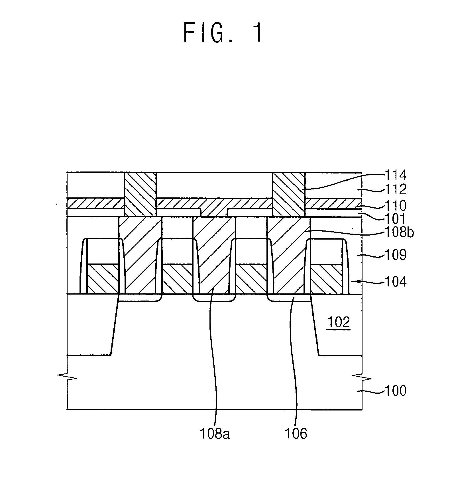
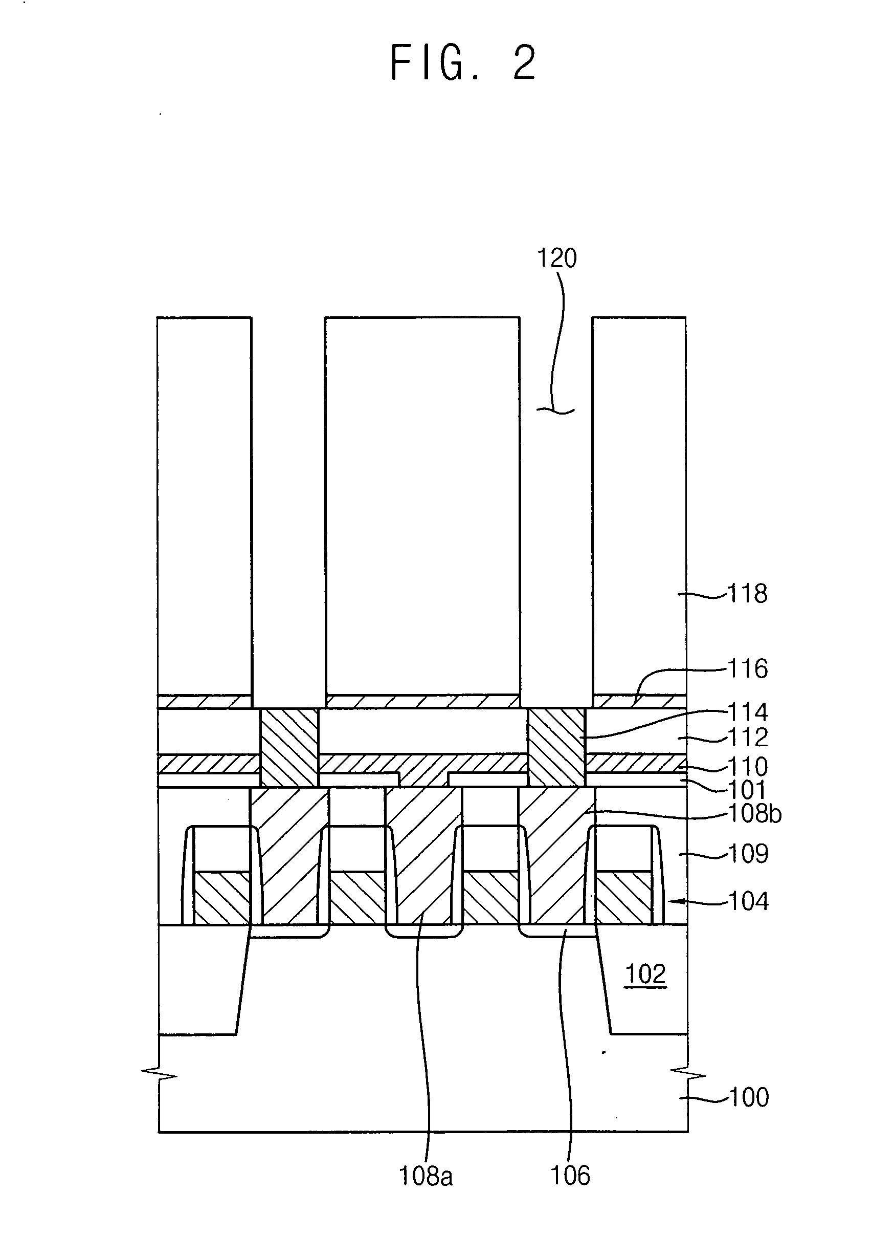
[0024] In another aspect, the present invention is directed to a method of manufacturing a semiconductor device. In the method of manufacturing the semiconductor device such as a DRAM device, a transistor is formed on a substrate, and then a first insulating interlayer is formed on the substrate. The first insulating interlayer includes a first pad electrode and a second pad electrode electrically connected to source / drain regions of the transistor. A second insulating interlayer is formed on the first insulating interlayer. The second insulating interlayer includes a bit line electrically connected to the first pad electrode. A third insulating interlayer is formed on the second insulating interlayer. The third insulating interlayer includes a contact plug electrically connected to the second pad electrode. A mold layer is formed on the third insulating interlayer. The mold layer includes an opening exposing the contact plug. A conductive layer is formed on the contact plug, an inner sidewall of the opening and the mold layer. A photoresist pattern is formed to substantially fill the opening, and a cylindrical lower electrode is formed by partially removing the conductive layer. The mold layer is selectively removed while the photoresist pattern prevents damage to the lower electrode and underlying structures. After removing the photoresist pattern, a dielectric layer is formed on the lower electrode and the third insulating interlayer. Then, an upper electrode is formed on the dielectric layer.
[0026] According to the present invention, since an etching solution will not permeate into the lower electrode and a contact plug electrically connected to a lower electrode of a capacitor during selective removal of the mold layer, damage to the lower electrode and the contact plug is effectively prevented. As a result, the semiconductor device fabricated accordingly will have improved electrical characteristics and reliability with reduced likelihood of failure.
[0027] In addition, the lower electrode of the capacitor can be formed without a CMP process so that the time and cost associated with manufacturing a semiconductor device including the capacitor can be reduced. Further, the capacitor includes a lower electrode of conductive material such as metal so that the capacitor can have an enhanced capacitance value.

Problems solved by technology

When the depletion layers are generated in the PIP capacitor, a dielectric layer of the PIP capacitor can have a relatively increased thickness, causing deterioration of the capacitance of the PIP capacitor.
In particular, when the PIP capacitor is employed for a highly integrated semiconductor device having a design rule of below about 90 nm, the semiconductor device may not have a desired capacitance.
When a galvanic coupling is formed between two different conductive layers or patterns, one of the conductive layers or patterns is especially susceptible to erosion.
As a result, a void may be generated between the contact plug and the lower electrode because the contact plug can become rapidly etched in the etching processes for forming the lower electrode.
However, the CMP process may require a relatively long time and also process conditions of the CMP process may not be easily controlled.
However, the conventional methods of manufacturing the lower electrode only provide a lower electrode having a concave structure of which only the interior portion is used as an effective area of the capacitor.
Hence, such a form of lower electrode is not suitable for use in a capacitor that is to be included in a highly integrated semiconductor device requiring a high storage capacitance.

Method used


Image

  • Methods of manufacturing a capacitor and a semiconductor device
  • Methods of manufacturing a capacitor and a semiconductor device
  • Methods of manufacturing a capacitor and a semiconductor device

Examples


Embodiment Construction

[0031] The present invention is described more fully hereinafter with reference to the accompanying drawings, in which embodiments of the present invention are shown. The present invention may, however, be embodied in many different forms and should not be construed as limited to the embodiments set forth herein. Rather, these embodiments are provided so that this disclosure will be thorough and complete. In the drawings, the sizes and relative sizes of layers and regions may be exaggerated for clarity.

[0032] It will be understood that when an element or layer is referred to as being “on”, “connected to” or “coupled to” another element or layer, it can be directly on, connected or coupled to the other element or layer or intervening elements or layers may be present. In contrast, when an element is referred to as being “directly on,”“directly connected to” or “directly coupled to” another element or layer, there are no intervening elements or layers present. Like reference numerals...


PUM


Abstract

In methods of manufacturing a capacitor and a semiconductor device, a mold layer is formed on a substrate having a contact plug. The mold layer includes an opening exposing the contact plug. A conductive layer is formed on the contact plug, an inner sidewall of the opening and the mold layer. A photoresist pattern is formed to substantially fill the opening. A cylindrical lower electrode is formed by partially removing the conductive layer. The mold layer is selectively removed while the photoresist pattern prevents damage to the lower electrode, the contact plug and the substrate. The photoresist pattern is removed, and then a dielectric layer and an upper electrode are sequentially formed on the lower electrode. Damage to the lower electrode and the contact plug are effectively prevented due to the presence of the photoresist pattern during selective removal of the mold layer.

Description

CROSS-REFERENCE TO RELATED APPLICATIONS [0001] This application claims priority under 35 USC § 119 to Korean Patent Application No. 2004-98538 filed on Nov. 29, 2004, the contents of which are herein incorporated by reference in its entirety. BACKGROUND OF THE INVENTION [0002] 1. Field of the Invention [0003] Example embodiments of the present invention relate to methods of manufacturing a capacitor and a semiconductor device. More particularly, example embodiments of the present invention relate to a method of manufacturing a capacitor having a lower electrode including metal and a method of manufacturing a semiconductor device such as a DRAM device including such a capacitor. [0004] 2. Description of the Related Art [0005] Semiconductor devices continue to be developed to have higher response speed, larger storage capacity and lower power consumption as information processing systems enjoy widespread use. Semiconductor devices are typically categorized into volatile semiconductor ...

Claims


Application Information

Patent Timeline
Patent Type & Authority Applications(United States)
IPC IPC(8): H01L21/20H01L21/8242H10B12/00
CPCH01L27/10817H01L27/10852H01L28/91H10B12/318H10B12/033H10B12/00
Inventor SHIM, WOO-SEOKPARK, YOUNG-WOOKLEE, JUNG-HYEONYOON, KWANG-SUBKIM, CHUL-HOPARK, TAE-JIN
Owner SAMSUNG ELECTRONICS CO LTD
Learn More