Plasma display panel

Inactive Publication Date: 2006-06-01
SAMSUNG SDI CO LTD
View PDF23 Cites 9 Cited by
  • Summary
  • Abstract
  • Description
  • Claims
  • Application Information

AI Technical Summary

Benefits of technology

[0012] In the plasma display panel according to the present invention, strength of the barrier ribs increases because the barrier ribs are integrally formed with the substrate. Further, when manufacturing the plasma display panel, processes of producing an upper plate and a lower plate are very similar and producing processes are simplified. Therefore, overall manufacturing cost decreases.
[0013] Further, in the plasma display panel according to the present invention, a discharge surface can be significantly widened because a surface-discharge can occur in all side surfaces forming discharge cells. Specifically, since the discharge takes place at side surfaces forming discharge cells and then spreads toward center portions of the discharge cells, a discharge area is significantly increased, compared to that of a conventional plasma display panel, whereby the whole space of the discharge cells can be efficiently utilized. As a result, the discharge can take place at a low voltage, whereby luminous efficiency is significantly increased.
[0014] Further, the plasma display panel according to the present invention has a structure in which a low-voltage driving is made possible. Therefore, even though highly-concentrated Xe gas is used as discharge gas, the low-voltage driving is made possible, whereby the luminous efficiency is improved.
[0015] Further, the plasma display panel according to the present invention has a structure in which discharge response speed is fast and a low-voltage driving is made possible. Specifically, the discharge electrodes are disposed in the barrier ribs, not on the front substrate through which visible rays penetrate. Accordingly, the discharge response speed is fast and a low-voltage driving is made possible without distorting waveforms because it is possible to use an electrode having low resistance, for example, a metal electrode instead of a transparent electrode having high resistance as a discharge electrode.
[0016] Further, in the plasma display panel according to the present embodiment, it is possible to substantially prevent permanent image sticking. Specifically, electric field prevents ions generated by discharge from colliding with the phosphor layers although the discharge continues for a period of time because it allows plasma to intensively gather at center portions of the discharge cells due to a voltage applied on the discharge electrodes formed at side surfaces of the discharge cells. Therefore, it is possible to substantially prevent lasting afterimage arising from damage to the phosphor layers caused by ion sputtering. Specifically, the lasting afterimage is a critical problem when the highly-concentrated Xe gas is used as discharge gas. However, in the present invention, it is possible to substantially prevent lasting afterimage.

Problems solved by technology

Therefore, overall manufacturing cost decreases.

Method used


Image

  • Plasma display panel
  • Plasma display panel
  • Plasma display panel

Examples


Embodiment Construction

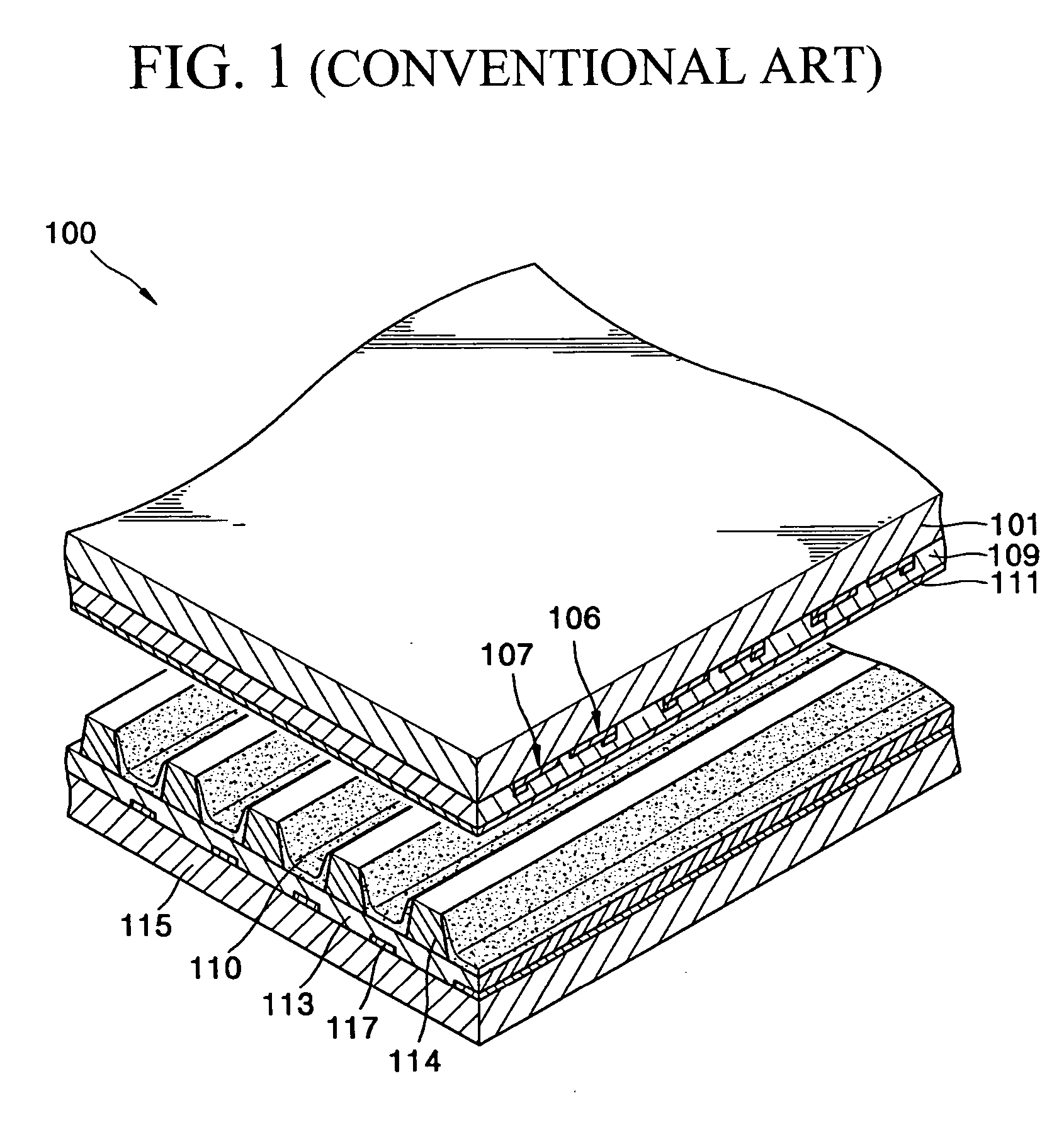
[0022] Turning now to the drawings, in the conventional three-electrode surface-discharge plasma display panel 100 shown in FIG. 1, visible rays emitted from the phosphor layers 110 are absorbed, to a large degree (about 40%), by the sustain electrodes 106, 107 disposed on the lower surface of a front substrate 101, dielectric layers 109 covering the electrodes 106, 107, and MgO films 111, whereby light emission efficiency decreases.

[0023] Further, in a case where the conventional three-electrode surface-discharge plasma display panel 100 displays the same image for a period of time, charged particles of discharge gas are implanted into the phosphor layers 110, whereby permanent image sticking occurs.

[0024] Furthermore, a producing process is complicated because address electrodes 117 and a lower dielectric layer 113 are formed on a back substrate 115 and barrier ribs 114 are separately formed on the lower dielectric layer 113.

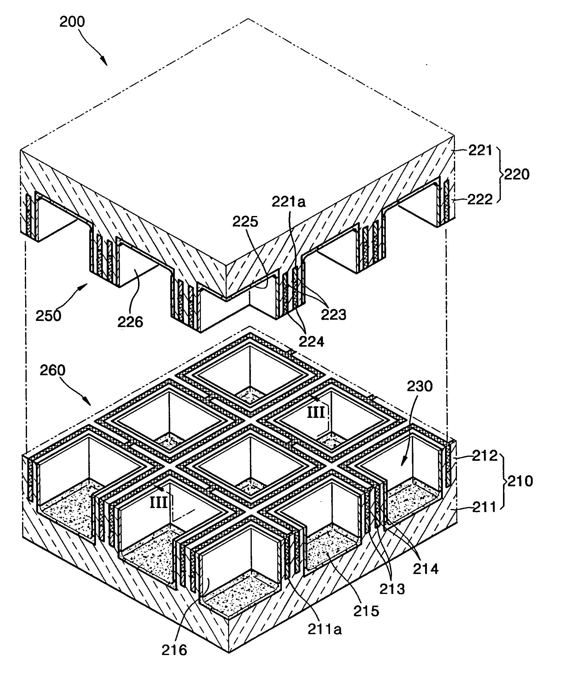
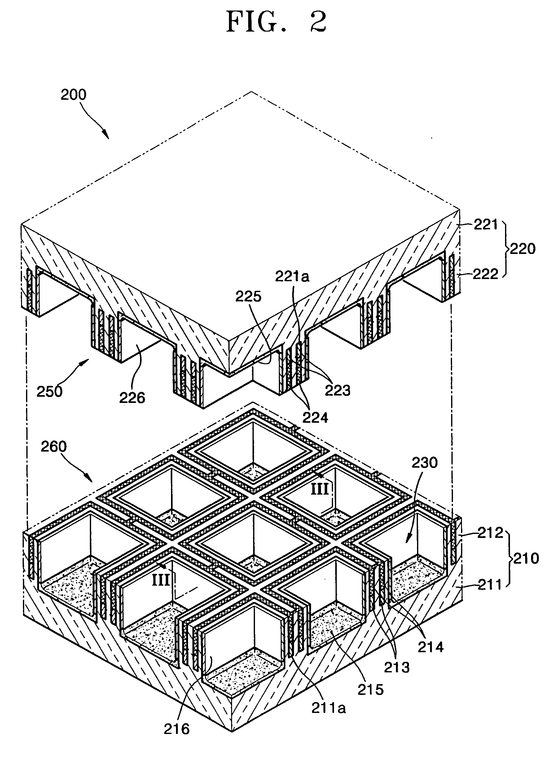
[0025] A plasma display panel 200 according to the em...


PUM


Abstract

A plasma display panel includes a back substrate having back barrier ribs partitioning a plurality of discharge cells; a front substrate arranged to be opposite to the back substrate and having front barrier ribs partitioning the discharge cells in cooperation with the back barrier ribs; back discharge electrodes arranged within the back barrier ribs to enclose the discharge cells; front discharge electrodes arranged within the front barrier ribs to enclose the discharge cells; phosphor layers arranged within the discharge cells; and discharge gas arranged within the discharge cells.

Description

CLAIM OF PRIORITY [0001] This application makes reference to, incorporates the same herein, and claims all benefits accruing under 35 U.S.C. § 119 from an application for PLASMA DISPLAY PANEL earlier filed in the Korean Intellectual Property Office on 29 Nov. 2004 and there duly assigned Serial No. 10-2004-0098742. BACKGROUND OF THE INVENTION [0002] 1. Field of the Invention [0003] The present invention relates to a plasma display panel, and more particularly, to a plasma display panel having a new structure. [0004] 2. Description of the Related Art [0005] In recent years, display apparatuses employing a plasma display panel as a flat display panel have been in wide use. Such display apparatuses have excellent characteristics such as high image quality, ultra thin thickness, small weight, and wide viewing angle, as well as large-sized screen. In addition, the display apparatuses can be simply manufactured and their size can be easily increased, compared to the others. Therefore, suc...

Claims


Application Information

Patent Timeline
IPC IPC(8): H01J17/49H01J11/14H01J11/16H01J11/22H01J11/24H01J11/32H01J11/34H01J11/36H01J11/38H01J11/40H01J11/42H01J11/50
CPCH01J11/16H01J11/22H01J11/36H01J11/24
Inventor KANG, KYOUNG-DOOYI, WON-JU
Owner SAMSUNG SDI CO LTD
Why Eureka
Try Eureka