Memory control circuit and microprocessor system

a memory control circuit and microprocessor technology, applied in program control, computation using denominational number representation, instruments, etc., can solve the problems of pipeline stoppage, flow stoppage, processing performance reduction, etc., and achieve the effect of reducing branch penalty and small circuit siz

Active Publication Date: 2006-05-04
CYPRESS SEMICON CORP
View PDF10 Cites 10 Cited by
  • Summary
  • Abstract
  • Description
  • Claims
  • Application Information

AI Technical Summary

Benefits of technology

[0010] In view of the foregoing, it is an object of the present invention to provide a memory control circuit that can reduce a branch penalty generated when a CPU executes a branch instruction and that has a small circuit size.
[0011] Another object of the present invention is to provide a microprocessor system that can reduce a branch penalty generated when a CPU executes a branch instruction and that has a small circuit size.

Problems solved by technology

In such a system, however, if an instruction branch occurs, instruction data read in advance by a pre-fetch cannot be used, the pre-fetch buffer is cleared, and the branch-destination instruction needs to be fetched.
Therefore, until new data reaches the CPU, the flow of the pipeline stops, and processing performance is reduced.
Therefore, the pipeline flow is stopped, and processing performance is reduced.
To increase the hit rate of the instruction cache memory, the data capacity of the instruction cache memory needs to be made larger, which increases the circuit size and manufacturing cost.
In the microprocessor system disclosed in Japanese Unexamined Patent Publication No. 9-305490 (1997), described above, since the counter for counting the number of times the instruction cache memory is used is provided, the circuit size and manufacturing cost are increased.
In this case, however, the size of the circuit which includes the instruction cache memory and the counter and manufacturing cost are increased.

Method used


Image

  • Memory control circuit and microprocessor system
  • Memory control circuit and microprocessor system
  • Memory control circuit and microprocessor system

Examples


first embodiment

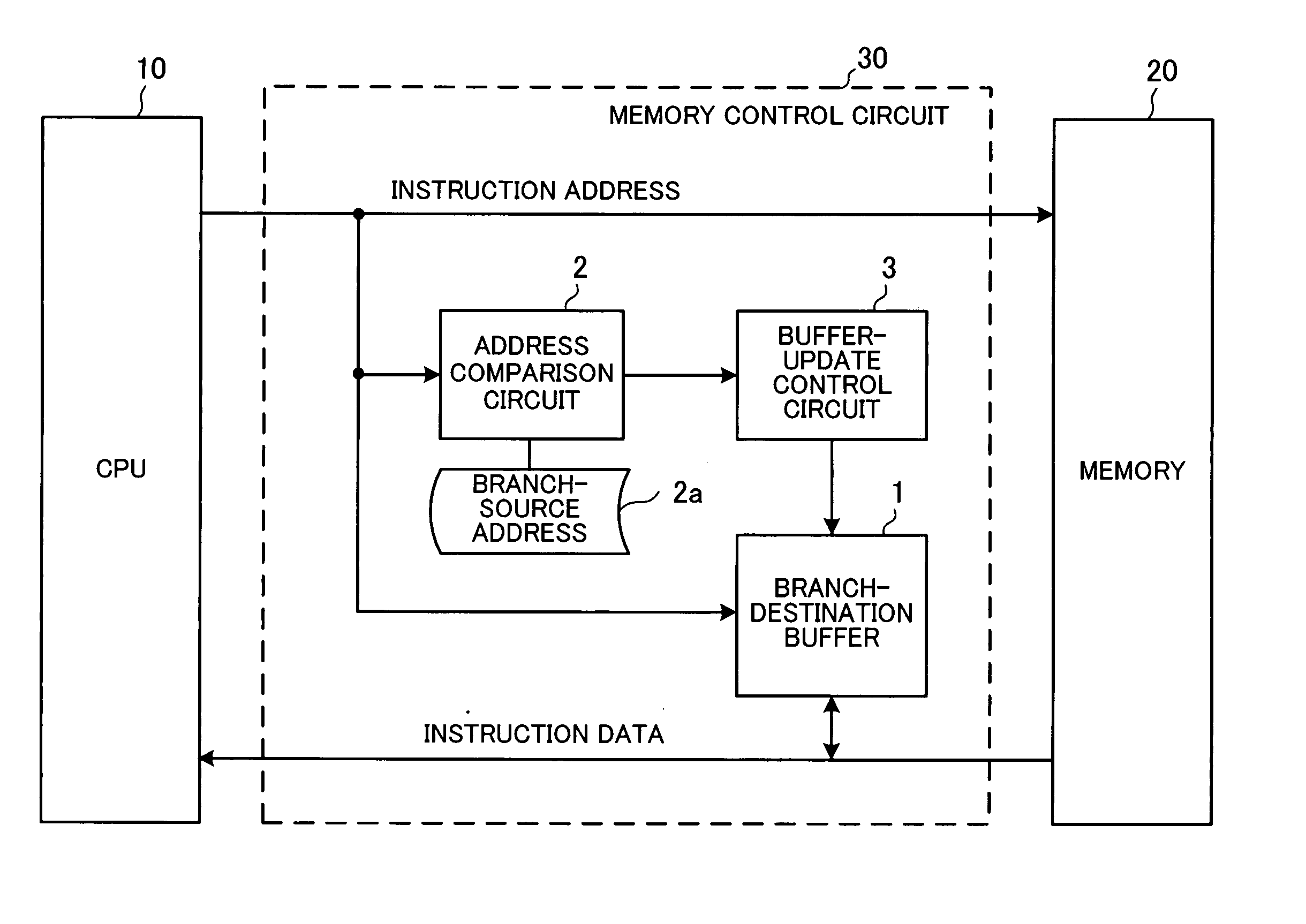
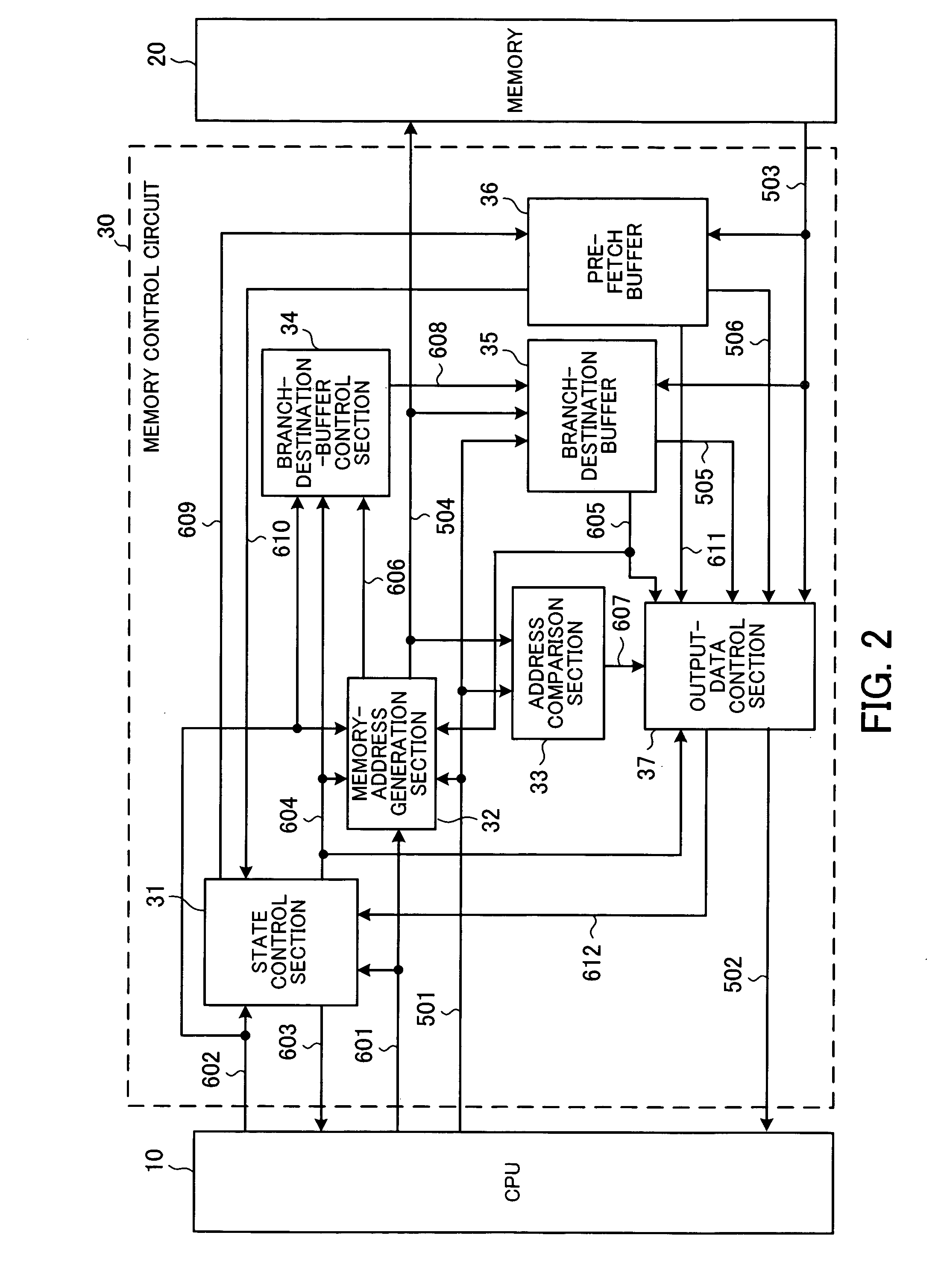
[0042]FIG. 2 shows the structure of a main part of a microprocessor system according to a first embodiment of the present invention.

[0043] The microprocessor system shown in FIG. 2 is applied to a so-called single-chip microcontroller and others. In this system, an access to a memory 20 needs the period of two cycles of a CPU clock signal. The width of a bus used for the data access is set two times wider than that for instruction code and an instruction-data pre-fetch function is used, so that an instruction can be sent to a CPU 10 in one cycle. It is assumed here as an example case that buses for instruction addresses and instruction data are 32 bits wide, instruction data is 16 bits wide, the CPU 10 can fetch two instructions at the same time once in two cycles of the CPU clock signal, and an access cycle for the memory 20 corresponds to two cycles of the CPU clock signal.

[0044] In this microprocessor system, the CPU 10 outputs the instruction address 501 of an instruction to b...

second embodiment

[0083] When it is only determined whether a branch-destination-instruction address is smaller than the previous-instruction address, as in the first embodiment, if a subroutine or an interrupt process is included in a loop, for example, it is not possible to determine whether the branch is a branch to the top of the loop of the program, which is the target to detect, or the branch is a branch caused by a subroutine call instruction or return instruction.

[0084]FIG. 7 is a flowchart showing an example program in which a subroutine process is included in a loop.

[0085] In FIG. 7, it is assumed that process codes in steps S21 to S23 are stored in that order in a memory space consecutive viewed from the CPU 10 as in FIG. 4. Step 23 performs a subroutine process.

[0086] In this figure, a “branch E” from step S25 to step S23 and a “branch F” from step S23 to step S21 both change the instruction address 501 in the negative direction. Therefore, the branch-destination buffer 35 is updated w...

third embodiment

[0095]FIG. 9 shows the structure of a microprocessor system according to a third embodiment. In FIG. 9, the same reference symbols as those used in FIG. 2 are assigned to the same sections as those shown in FIG. 2, and a description thereof is omitted.

[0096] In the second embodiment, the branch-destination-buffer control section 34 determines whether a subroutine branch has occurred. In the present embodiment, whether a subroutine branch has occurred is determined by a subroutine-branch report signal 613 sent from a CPU 10. When the CPU 10 decodes a subroutine call instruction or a subroutine return instruction, the CPU 10 asserts the subroutine-branch report signal 613 to report to a branch-destination-buffer control section 34 of a memory control circuit 30 that a subroutine branch has occurred.

[0097]FIG. 10 shows the internal structure of the branch-destination-buffer control section 34 according to a third embodiment. In FIG. 10, the same reference symbols as those used in FIG...


PUM


Abstract

A memory control circuit for providing a small-circuit-size memory control circuit capable of reducing a branch penalty during the execution of a branch instruction in a CPU. A branch-destination buffer caches a branch-destination instruction and a branch-destination-instruction address determined by a branch instruction executed by the CPU. When the CPU executes a branch instruction thereafter, if the branch-destination-instruction address output from the CPU matches an instruction address in the branch-destination buffer, the corresponding branch-destination instruction stored in the branch-destination buffer is sent to the CPU. When a branch instruction is executed, an address comparison circuit compares the branch-destination-instruction address with the branch-source-instruction address. A buffer-update control circuit updates data of the branch-destination buffer by the branch-destination instruction only when it is determined according to the result of comparison performed by the address comparison circuit that the instruction address has been changed in the negative direction by the instruction branch.

Description

CROSS-REFERENCE TO RELATED APPLICATIONS [0001] This application is based upon and claims the benefits of priority from the prior Japanese Patent Application No. 2004-258651, filed on Sep. 6, 2004, the entire contents of which are incorporated herein by reference. BACKGROUND OF THE INVENTION [0002] 1. Field of the Invention [0003] The present invention relates to memory control circuits provided with an instruction pre-fetch function, for controlling the reading of instructions to be fetched by the CPU, from a memory and microprocessor systems that include the memory control circuits, and particularly to a memory control circuit and a microprocessor system both having a reduced penalty-cycle occurrence rate during the execution of branch instructions. [0004] 2. Description of the Related Art [0005] It has been conventionally known in microprocessor systems which use pipeline control that instruction data is read in advance from a main memory and buffered by an instruction pre-fetch f...

Claims


Application Information

Patent Timeline
Patent Type & Authority Applications(United States)
IPC IPC(8): G06F9/00
CPCG06F9/3804
Inventor FURUYA, KENJI
Owner CYPRESS SEMICON CORP
Why Eureka
Try Eureka