
System, software arrangement and method for segmenting an image

a software arrangement and image technology, applied in image enhancement, medical/anatomical pattern recognition, instruments, etc., can solve the problems of low accuracy of bse approach, low accuracy of conventional approach, and general poor precision of bse approach, so as to simplify the access to individual labels, reduce the amount of data to be accessed, and improve the effect of image quality

Active Publication Date: 2006-05-04
NEW YORK UNIV
View PDF3 Cites 17 Cited by
  • Summary
  • Abstract
  • Description
  • Claims
  • Application Information

AI Technical Summary

Benefits of technology

[0020] Although each label can be of any bit length, according to one exemplary embodiment, BYTE (8-bit) labels may be used. Each label can also be interpreted as an isotropic vertex of the voxel. Each voxel of the original volume can have 8 vertexes. These vertexes form a cube with the sides of length “1” in three dimensions. This minimizes amount of data to be accessed during the processing of the algorithm, while simplifying the access to individual labels, thus resulting in a robust performance.
[0021] An exemplary embodiment of the present invention utilizes a 26-neighbor connectivity model. For example, vertex of the isotropic 3d lattice may have exactly 26 neighbors. Each neighbor has a different distance from the parent. In the three-dimensional case, possible distances may be 1 unit, which can equal to a spacing of the isotropic 3d lattice, the square root of 2, and the square root of 3 (based on the distance from vertex to vertex in the cube arrangement). The wavefront propagation algorithm which can be used according to the present invention can take into account those differences, thus facilitating a better approximation of an ideal spherical wavefront than conventional algorithms, because, e.g., because the difference between various spatial directions may be smaller. In addition, a user is able to specify a fractional number (e.g., in voxels) of Peels. Fractional numbers generally provide a better discrimination power in the practical applications, for example, when the critical organ dimension to be imaged is very small (e.g., the thickness of a colon fold can be somewhere between 1-2 voxels).
[0022] Further, the wavefront according to an exemplary embodiment of the present invention can be propagated through voxel vertex. This allows a resolution of certain edge-related contradictions, which may not have been possible under conventional voxel propagation models.
[0024] According to another exemplary embodiment of the present invention, third data can be provided that is associated with a volume of a soft tissue of the portion based on the first data; and the second data may be with the third data to obtain fourth data. In this manner, it is possible to separate anatomically distinct and adjacent sections of the at least one portion from one another. The image may be generated further based on the fourth data. The third data may include information regarding surface voxels associated with the portion. Further data associated with the surface voxels can be processed so as to generate connected voxel components. In this manner, the image can be generated further based on the connected voxel components. In addition, the surface voxel can be eroded morphologically, and the connected voxel components may be ordered according sizes thereof.

Problems solved by technology

A segmentation of the brain tissue is one of the most time-consuming preprocessing steps performed in neuro-imaging laboratories.
Such conventional algorithms may generally enhance the speed of overall image processing, but still have various drawbacks.
Similarly to any intensity-only based method, the drawback of this conventional approach is low accuracy.
The drawback to such BSE approach is generally poor precision.
Further, using a 2D edge detector on 3D data generally provides little benefit, since such algorithm may not exploit the correlation of edges across adjacent slices.
Due, in part, to the iterative nature of this technique, the execution time of such approach generally makes it unsuitable for a routine use, even though there may be a good the precision.
However, conventional colon screening options have important limitations.
Screening sigmoidoscopy generally fails to evaluate the entire colon, may miss many advanced proximal carcinomas.
However, there are several important limitations to the widespread use of screening colonoscopy including need for sedation, potential risk of perforation and bleeding, costs of the procedure including the need for sedation, failure to complete the examination in 5-10% of patients, and an insufficient workforce of trained endoscopists to meet the demand (15,16).
One of important limitation of conventional colonoscopy is that in order to perform the examination, the colon must be thoroughly cleansed of residual fecal material.
Patients find bowel cleansing the most difficult aspect of screening, whether sigmoidoscopy, DCBE, or colonoscopy is used.
Bowel cleansing may be a major impediment to widespread CTC, it is judged uncomfortable (e.g., by about 89% of patients) and inconvenient (e.g., by about 78% of patients).
Given the limitations of current bowel preparations, including poor patient compliance as well as residual fecal material that can make interpretation difficult, the possibility of fecal and fluid tagging for CTC has been investigated.
This is an undesirable side effect.
Moreover, a purely threshold-based technique is clearly unable to remove incompletely tagged fecal matter.
This is a limitation, since despite the best effort to tag fecal material, there are always be some poorly or partially tagged fecal matter remaining.

Method used


Image

  • System, software arrangement and method for segmenting an image
  • System, software arrangement and method for segmenting an image
  • System, software arrangement and method for segmenting an image

Examples


Embodiment Construction

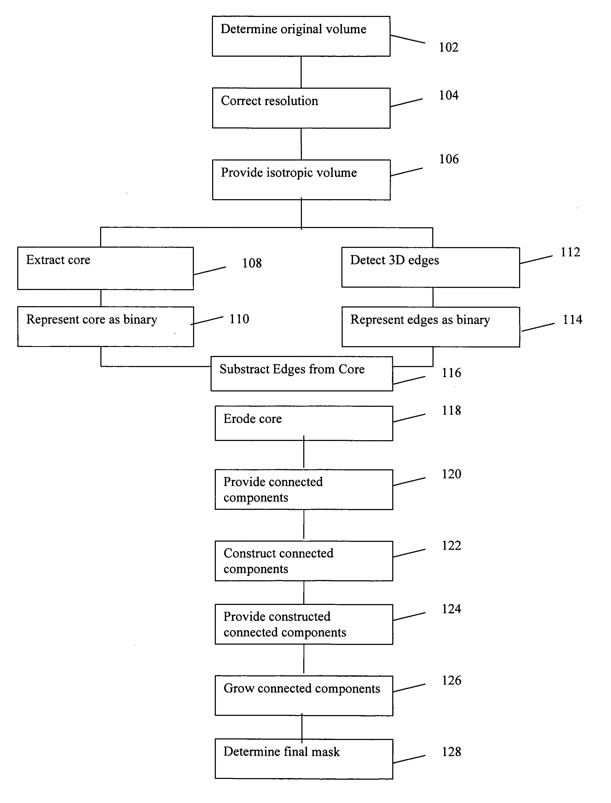
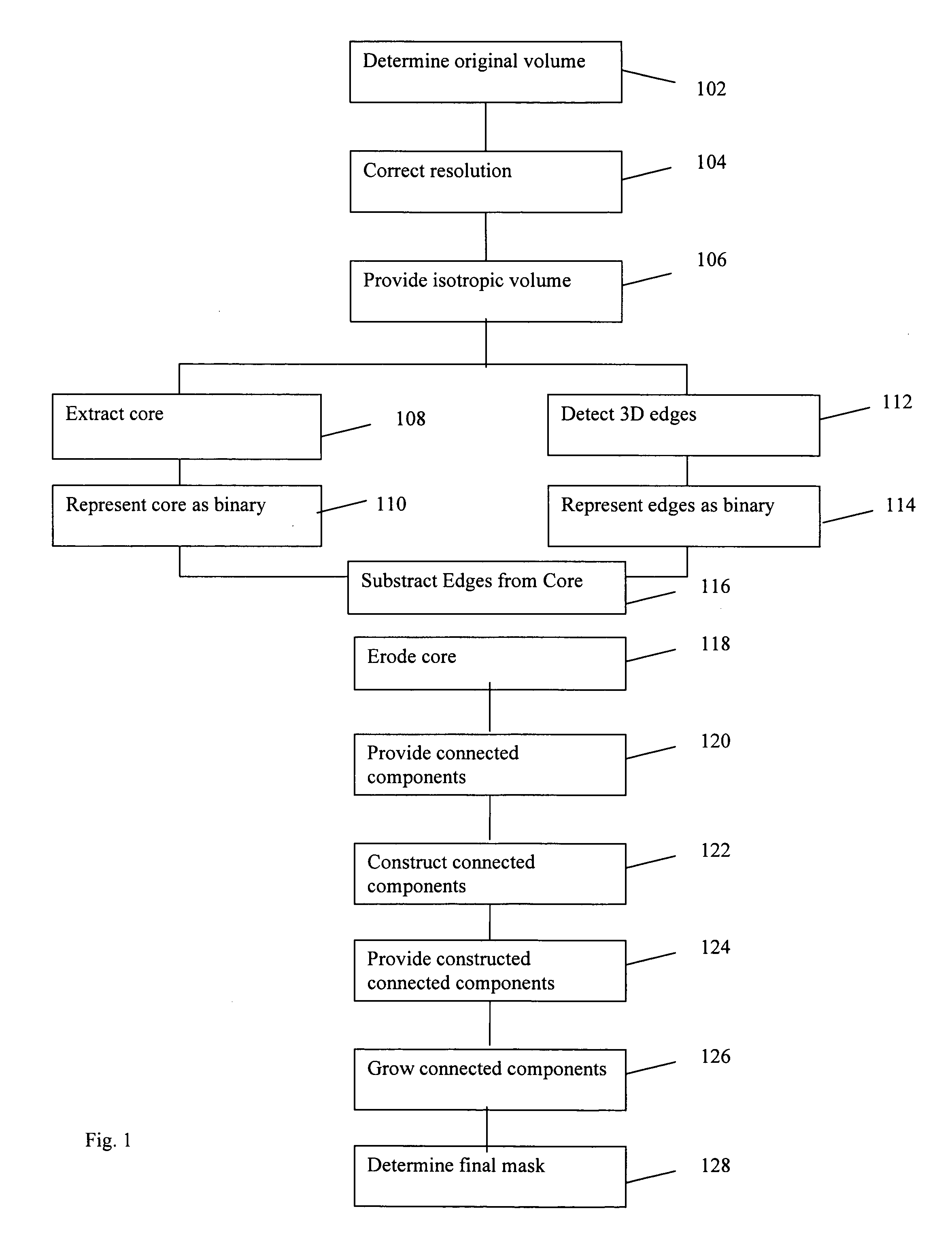
[0045]FIG. 1 depicts a flow diagram of an exemplary segmentation procedure in accordance with one exemplary embodiment of the present invention. Such segmentation can use attenuation, 3-dimensional connectivity and presences of edges to separate one anatomical body from another. For example, in step 102, 3-dimensional volumetric data of the head or another anatomical part (e.g., the colon) may be represented as a 3D voxel array using conventional MRI techniques so as to obtain an image, as it is know in the art. The voxels may be comprised of 16-bit data segments (but may be used for any bit depth). In step 104, the image obtained in step 102 may be resampled to make the voxels isotropic, e.g., thereby correcting the image. Isotropy refers to the resolution of the modified volume that can be identical or substantially similar along each of the X, Y, and Z axes. One of the purposes of step 104 is to improve the behavior of subsequent erosion and growth operations (as discussed herein...


PUM


Abstract

A logic arrangement, system and method for segmentation using magnetic resonance imaging (“MRI”) are provided. For example, as an end product, an image associated with at least one portion of an anatomical structure is generated. In particular, first data associated with the at least one portion of the anatomical structure is received. Second data can be associated with at least one edge of at least one of the at least one portion is obtained based on the first data. The image can be generated based on the first data and the second data. In addition or as an alternative, it is also possible to generate the image using connected voxel components. Such components are created by processing information associated with an erosion of surface voxels of an image.

Description

CROSS-REFERENCE TO RELATED APPLICATION(S) [0001] This application claims priority from U.S. Patent Application No. 60 / 623,840, filed on Oct. 29, 2004, the entire disclosure of which is incorporated herein by reference.FIELD OF THE INVENTION [0002] The present invention relates generally to imaging software arrangements, methods and systems, which can use magnetic resonance (“MR”), computed tomography (CT), and / or any other imaging techniques. In particular the present invention relates to software arrangements, methods for image segmentation from magnetic resonance imaging (“MRI”), and to systems and software arrangements utilizing such methods. BACKGROUND INFORMATION [0003] Magnetic Resonance Imaging (“MRI”) systems generally use strong magnetic fields in order to polarize the magnetic spins of nuclei to be imaged, and to create the magnetic resonance condition therein. [0004] Numerous clinical and research applications related to brain imaging using MRI, Computerized Tomography (“...

Claims


Application Information

Patent Timeline
Patent Type & Authority Applications(United States)
IPC IPC(8): A61B8/00
CPCA61B5/055A61B6/03G06K9/4638G06K2209/05G06T7/0083G06T2207/10081G06T2207/10088G06T2207/20036G06T2207/20104G06T2207/30016G06T2207/30032G06T7/12G06V10/457G06V2201/03
Inventor MIKHEEV, ARTEMRUSINEK, HENRY
Owner NEW YORK UNIV
Learn More