Structure, optical device, magnetic device, magnetic recording medium and manufacturing method thereof
- Summary
- Abstract
- Description
- Claims
- Application Information
AI Technical Summary
Benefits of technology
Problems solved by technology
Method used
Image
Examples
embodiment 1
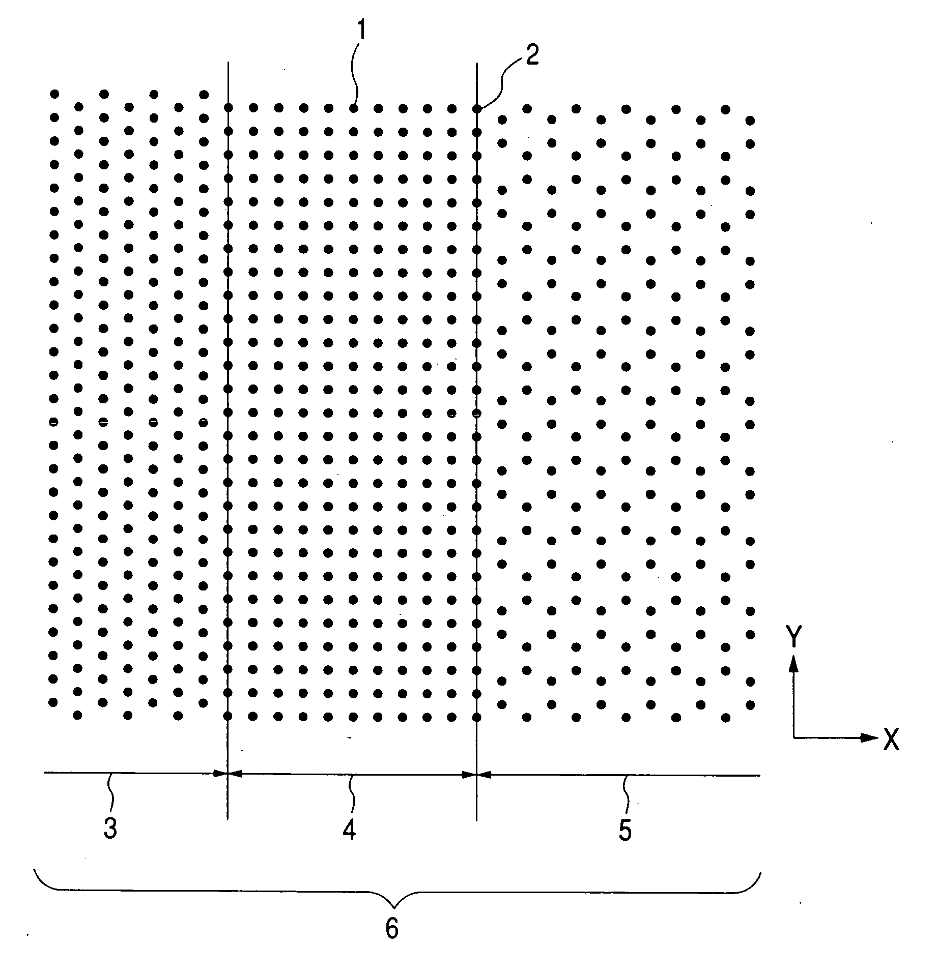
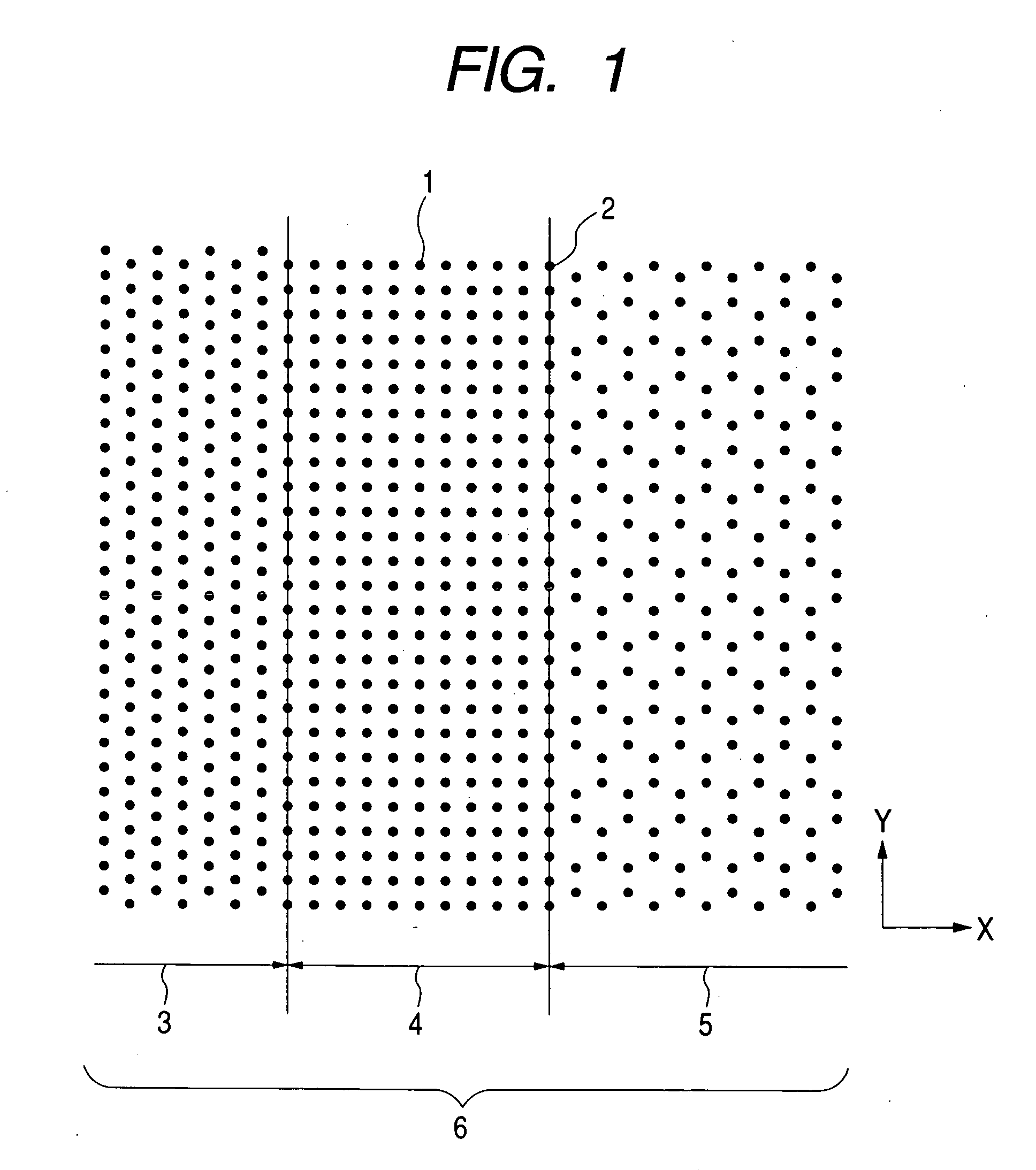
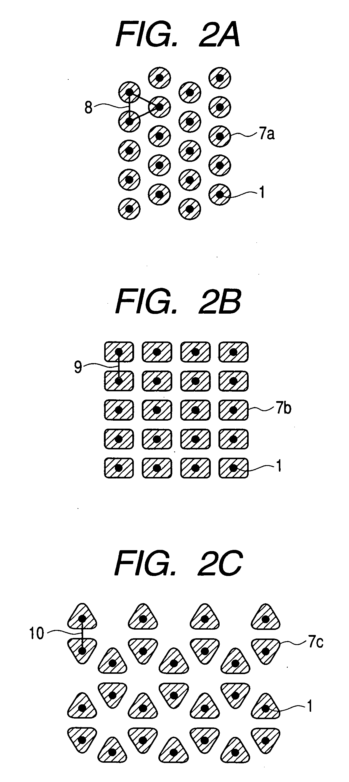
[0055] First, as step (2), concave structures having desired arrays are formed on the surface of a substrate on which an aluminum thin film is formed using an electron beam direct drawing method and these are used as pore starting points. As shown in FIG. 1, the array of pore starting points 1 consists of a hexagonal lattice area 3, a rectangular lattice area 4 and a graphite-shaped lattice area 5 arranged adjacent to one another and pores on the boundary of the adjacent areas are shared by both areas. That is, the two adjacent areas share an array of pores with equal periodicity on the boundary. Black bullets 1 in FIGS. 2A to 2C indicate projected positions of pores on a plane of the hexagonal lattice area, rectangular lattice area and graphite-shaped lattice area in FIG. 1. In FIGS. 2A to 2C, a period 8 of the hexagonal lattice area 3 is 200 nm, a period of the rectangular lattice area 4 in the Y direction 9 is 200 nm, that of the X direction is 250 nm and the most proximate dista...
embodiment 2
[0058] As a magnetic device, pores with hexagonal lattice areas and rectangular lattice areas having the same period as that of Embodiment 1 which are repeatedly arranged adjacent to one another are formed. FIG. 3 shows arrays of pores. The method of formion is the same as that in Embodiment 1. Cobalt is charged into the pores formed by an electric plating method to convert the area to a magnetic recording area. In this magnetic device, a direction 13 is regarded as the track orientation and the magnetic device is used, divided into a servo area 11 and data area 12. Some magnetic substance cell groups in the servo area are half a period shifted from the period of the magnetic substance cell groups in the direction perpendicular to the track direction and this is effective for performing position control (called “off track”) of the head and tracks. This prevents information of the adjacent tracks from being mistakenly reproduced or information from being overwritten on the already re...
embodiment 3
[0059] As a device, pores with hexagonal lattice areas arranged on both sides of a rectangular lattice area are formed. The method of formion is the same as that of Embodiment 1 and then polystyrene with light-emitting pigment is charged into the pores. Since the photonic band structure of the rectangular lattice area is different from that of the hexagonal lattice area, wavelengths which are easily guided vary depending on their respective structures. For this reason, when light wave which propagates through the rectangular lattice area but does not propagate through the hexagonal lattice area is introduced into the pores in the rectangular lattice area in the vertical direction 16 (see FIG. 4) and if this structure is regarded as a light waveguide, the rectangular lattice area becomes a core and the hexagonal lattice area becomes a cladding and light wave propagates with lower loss compared with a normal two-dimensional light waveguide. Filling arbitrary pores in the core area wit...
PUM
| Property | Measurement | Unit |
|---|---|---|
| Digital information | aaaaa | aaaaa |
| Digital information | aaaaa | aaaaa |
| Structure | aaaaa | aaaaa |
Abstract
Description
Claims
Application Information
 - R&D
- Intellectual Property
- Life Sciences
- Materials
- Tech Scout
- Unparalleled Data Quality
- Higher Quality Content
- 60% Fewer Hallucinations
Browse by: Latest US Patents, China's latest patents, Technical Efficacy Thesaurus, Application Domain, Technology Topic, Popular Technical Reports.
© 2025 PatSnap. All rights reserved.Legal|Privacy policy|Modern Slavery Act Transparency Statement|Sitemap|About US| Contact US: help@patsnap.com


