
Cache memory system

a memory system and cache technology, applied in the field of cache memory system, can solve the problems of critical processing delay, no bus load measurement, bus traffic, etc., and achieve the effects of preventing an increase of local bus traffic, stable moving picture processing, and small bus load

Inactive Publication Date: 2006-04-20
PANASONIC CORP
View PDF7 Cites 37 Cited by
  • Summary
  • Abstract
  • Description
  • Claims
  • Application Information

AI Technical Summary

Benefits of technology

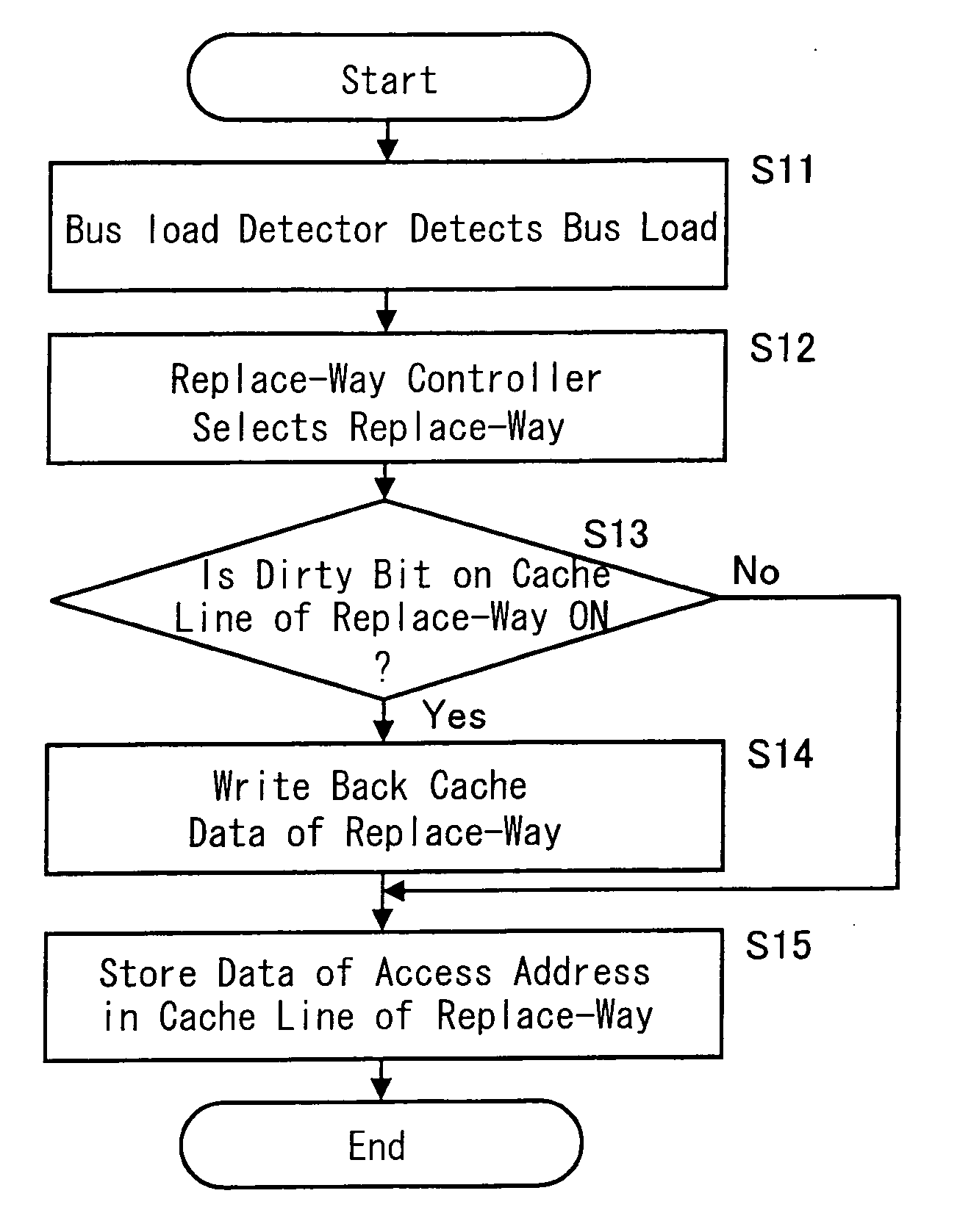
[0017] Further, it is preferable that the replace-way controller perform replacement by giving priority to a way which is not exclusive-discordant when the bus load is judged as valid by the bus load judging device, while performing replacement by giving priority to a way which is exclusive-discordant when the bus load is judged as invalid. With this, at the time of replacing the cache, it is possible to select the replacing form without write-back having a small bus load when there is the bus load being generated. Further, when there is no bus load, the bus can be utilized without a waste by giving priority to perform the replacing form with write-back having a large bus load.
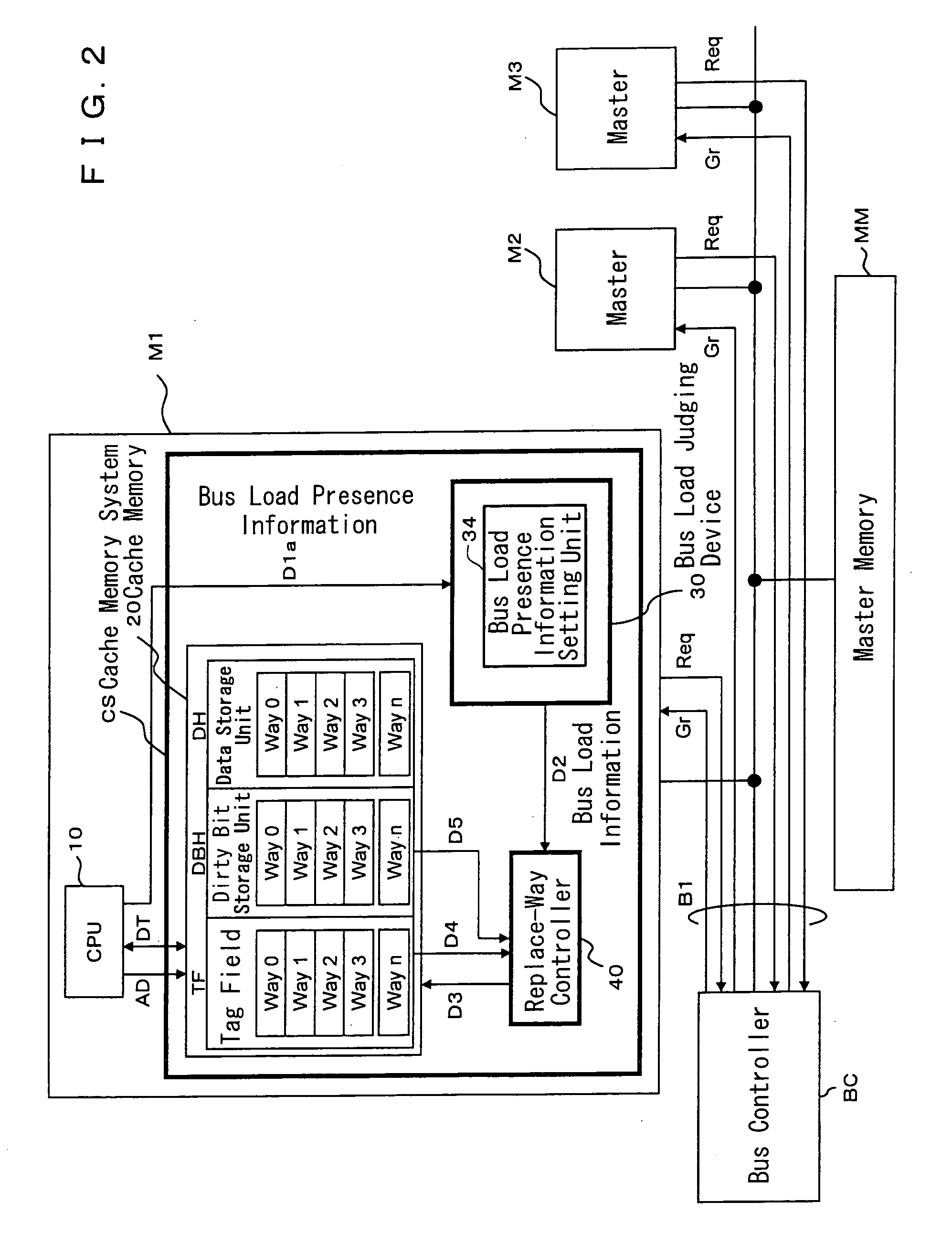
[0020] Furthermore, it is desirable that the bus load judging device comprise a bus load presence information setting unit which can set presence of the bus load from outside of the device, and that the bus load judging device judge validity / invalidity of the bus load according to a set state of the bus load presence information setting unit. With this, it becomes possible to change the replacing form at the optimum timing by having a user who writes a program sets the validity / invalidity of the bus load. Thus, the bus can be effectively utilized.
[0024] With the moving picture processor of the present invention having the above-described structures, it is possible to prevent an increase of a local bus traffic, i.e. a local memory access latency (waiting time) which causes a system breakdown. Therefore, stable moving picture processing can be executed.
[0025] As described above, with the present invention, it is possible to change the replacing structure of the cache memory in accordance with the bus load. That is, when there is a bus load, the replacement processing with small bus load is performed. When there is no bus load, the replacement processing with a large bus load is performed. Thereby, the bus can be effectively utilized and the local bus traffic can be improved. Thus, the bus traffic can be made uniform. Furthermore, since the bus load is made uniform, it is possible at the time of designing the bus width to set the optimum bus width. Moreover, with the moving picture processor, it is possible to prevent the system failure such as missing of a frame, etc.

Problems solved by technology

However, in the related art, although it enables to reduce the number of write-back by switching the above-described structures (1) and (2), there is no measure taken for bus load.
In a processor such as a DSP (Digital Signal Processor), which requires real-time processing, the bus traffic becomes a factor for critical processing delay.

Method used


Image

  • Cache memory system
  • Cache memory system
  • Cache memory system

Examples


Embodiment Construction

[0040] Embodiments of the cache memory system according to the present invention will be described in detail by referring to the accompanying drawings.

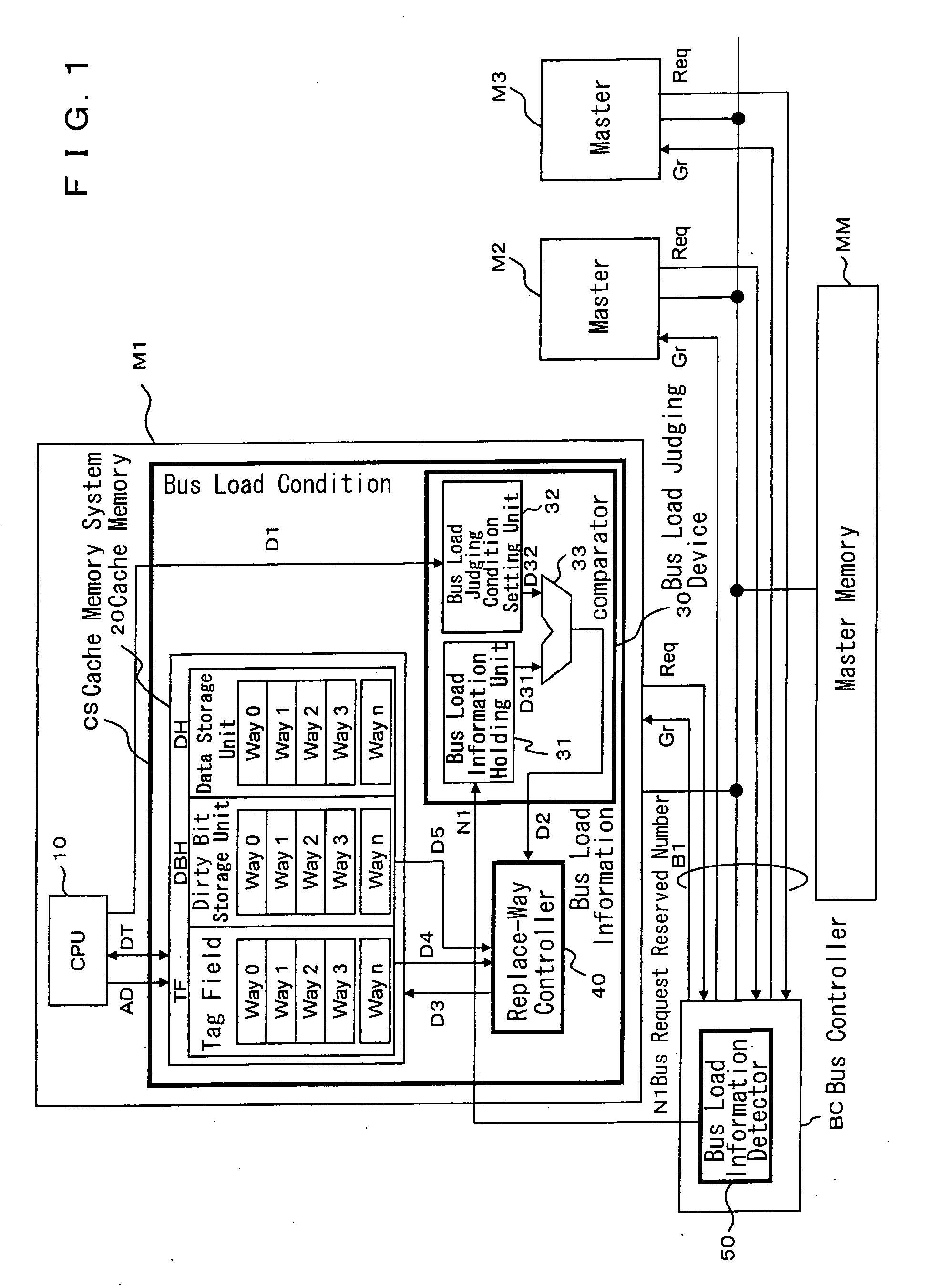
[0041]FIG. 1 is a block diagram for showing the structure of the cache memory system according to a first embodiment of the present invention. FIG. 2 is a block diagram for showing the structure of the cache memory system according to a second embodiment of the present invention.

[0042] The cache memory system of FIG. 1 comprises: three masters M1-M3, a bus controller BC having a bus load information detector 50, a master memory MM, and a bus B1. The master M1 carries a CPU 10 and a cache memory system CS. The cache memory system CS comprises a cache memory 20 of a write-back system, a bus load judging device 30, and a replace-way controller 40. The cache memory system CS is an n-way set associative system. By way of example, the cache memory system CS of this embodiment employs 4-way set associative system.

[0043] The cache memory 2...


PUM


Abstract

Provided is a cache memory system which, in a system having a plurality of masters, effectively utilizes a bus band. The cache memory system comprises: a cache memory; a bus load judging device for performing judgment of a state of a bus that is connected to a recording device in which cache-target data of the cache memory is stored; and a replace-way controller for controlling a replacing form of the cache memory according to a result of judgment performed by the bus load judging device.

Description

BACKGROUND OF THE INVENTION [0001] 1. Field of the Invention [0002] The present invention relates to a cache memory system and, particularly, to a replace technique which employs write-back of a multi-way set associative system. [0003] 2. Description of the Related Art [0004] It is known in a cache memory system that two structures in the followings enable to determine which data block is to be replaced when there is a cache error. [0005] (1) a structure for selecting data block according to access state [0006] (2) a structure for selecting data block by fixed priority according to a state of cache memory [0007] Examples of the structure (1) may be a structure (referred to as an LRU (Least Recently Used) structure) which replaces a data block that was accessed least recently, and a structure (referred to as FIFO (First In First Out) structure) which replaces a data block that was replaced least recently. Among the methods for achieving the structure (2), there is a structure which r...

Claims


Application Information

Patent Timeline
Patent Type & Authority Applications(United States)
IPC IPC(8): G06F12/00
CPCG06F12/126G06F12/127
Inventor MIYASHITA, TAKANORISHIBATA, KOHSAKUTSUBATA, SHINTARO
Owner PANASONIC CORP
Learn More