Belt type continuous plate manufacturing device and method of manufacturing sheet polymer

a technology of continuous plate and manufacturing device, which is applied in the direction of dough shaping, manufacturing tools, instruments, etc., can solve problems such as local irregularities, and achieve the effect of high plate thickness precision

Inactive Publication Date: 2006-04-06
MITSUBISHI RAYON CO LTD
View PDF6 Cites 8 Cited by
  • Summary
  • Abstract
  • Description
  • Claims
  • Application Information

AI Technical Summary

Benefits of technology

[0014] Also, the present inventors have investigated a way to keep the surface of an endless belt flat, and found that the reason for occurrence of optical strain along the belt running direction at the intermediate position between spray nozzles spraying mutually different heating media is that thermal expansion speed of both side edge portions is too larger than that of the center portion in the width direction of the endless belt to cause shift due to thermal deformation, leading to local irregularity. Then, the thermal expansion speed of an endless belt has been intensively investigated, and resultantly it has been found that if the speed of the temperature rising of an endless belt (hereinafter, abbreviated simply “temperature rising rate” in some cases) is set in a specific range, thermal deformation of an endless belt progresses substantially uniformly, and a plate polymer of extremely high plate thickness precision and having no optical strain along the width direction is obtained.

Problems solved by technology

Also, the present inventors have investigated a way to keep the surface of an endless belt flat, and found that the reason for occurrence of optical strain along the belt running direction at the intermediate position between spray nozzles spraying mutually different heating media is that thermal expansion speed of both side edge portions is too larger than that of the center portion in the width direction of the endless belt to cause shift due to thermal deformation, leading to local irregularity.

Method used


Image

  • Belt type continuous plate manufacturing device and method of manufacturing sheet polymer
  • Belt type continuous plate manufacturing device and method of manufacturing sheet polymer
  • Belt type continuous plate manufacturing device and method of manufacturing sheet polymer

Examples


example 1

[0085] To 100 parts of a methyl methacrylate syrup (viscosity: 1 Pa·s, 20° C.) having a degree of polymerization of 20% was added 0.1 part of tert-hexyl peroxypivalate (manufactured by NOF Corp., trade name: Perhexyl PV) as a polymerization initiator and 0.005 parts of sodium dioctylsulfosuccinate as a releasing agent and they were uniformly mixed, to obtain a liquid polymerizable raw material. This polymerizable raw material was de-foamed in a vacuum vessel, and applied to the apparatus in FIG. 1 to produce a plate product 1 having a thickness of 5 mm and a width of 1300 mm.

[0086] In this example, the apparatus in FIG. 1 has a total length of 10 m, two stainless endless belts 1, 1′ have a thickness of 1.5 mm and a width of 1.5 m, and both of them are given a tension of 3.0×10⁷ Pa by oil pressure. As the gasket 7, a gasket made of a polyvinyl chloride is mounted.

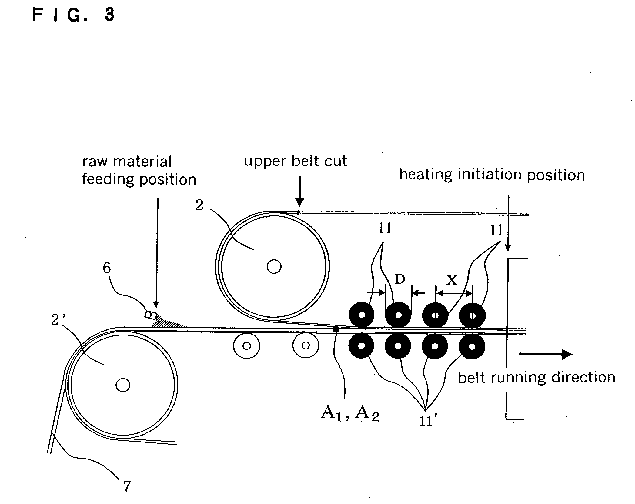
[0087] In a district from the raw material feeding position to the heating initiation position, four upper and lower rol...

example 2

[0091] A plate product 2 was obtained in the same manner as in Example 1 excepting use of a roll pair composed of flat rolls having an outer diameter of a stainless body portion of 130 mm, an outermost diameter D including a rubber part of 150 mm, a width Z of 1600 mm, a stainless wall thickness of 5 mm, an outer diameter of a solid axis of 20 mm, a width of a solid axis of 125 mm and a tolerance of the outermost diameter of 0.1 mm or less, so regulated that the distance between axes of upper and lower rolls was 160.0 mm, as the second upper and lower roll pair from the raw material feeding position side among four upper and lower roll pairs 11, 11′ in a district from the raw material feeding position to the heating initiation position in the apparatus shown in FIG. 1. In this second upper and lower roll pairs 11, 11′ from the raw material feeding position side, D / Z=0.094, and D / X=0.75.

example 3

[0092] A polymerizable raw material was de-foamed in a vacuum vessel, then, a plate product 3 having a thickness of 3 mm and a width of 2800 mm was produced by an apparatus as shown in FIG. 1 which is further larger than that in Example 1.

[0093] In the apparatus shown in FIG. 1 in this example, the total length is 100 m, and two stainless endless belts 1, 1′ have a thickness of 1.5 mm and a width of 3 m, and are given a tension of 8.0×10⁷ Pa by oil pressure. As the gasket 7, a gasket made of a polyvinyl chloride is mounted.

[0094] In a district from the raw material feeding position to the heating initiation position, eight upper and lower roll pairs 11, 11′ in total are arranged at constant interval so that the arrangement distance X of the rolls is 350 mm. The body portion of each roll of the upper and lower roll pairs 11, 11′ is made of stainless having a hollow core section, and the outer part thereof is coated with rubber, further, stainless solid axes are provided on both end...


PUM

PropertyMeasurementUnit
Temperatureaaaaaaaaaa

Abstract

A belt type continuous plate manufacturing apparatus comprising two facing endless belts 1, 1′ and gaskets 7 sandwiched by belt surfaces at their both side edge portions, wherein a polymerizable raw material is fed into a space surrounded by the facing belt surfaces and the gaskets 7 from its one end, the polymerizable raw material is solidified together with running of the belts in a heating zone, and the plate polymer is taken out from the other end, characterized in that three or more upper and lower roll pairs satisfying the following formulae (1) and (2) are placed so that respective axes thereof orthogonally cross the belt running direction, between a raw material feeding position and a heating initiation position; and a method of producing a plate polymer by using it: D / Z≧0.04 (1), 0.30≦D / X≦0.99 (2) [D=outermost diameter of roll body portion (mm), Z=width of roll body portion (mm), X=distance between axis centers of adjacent upper and lower roll pairs (mm)].

Description

TECHNICAL FIELD [0001] The present invention relates to a belt type continuous plate manufacturing apparatus of producing a plate product (i.e., plate polymer) by continuously polymerizing a polymerizable raw material, and a method of producing a plate polymer using this apparatus. BACKGROUND ART [0002] Plate polymers obtained from methyl methacrylate as the main raw material are used in signboard and building material applications, sanitary application such as baths and the like, illumination application, and other wider fields, utilizing their excellent properties. Recently, they are used as a light transmission plate of displays such as liquid crystal displays, and its demand is increasing steeply, also because of world wide spreading of the IT technology. [0003] Of course, such a light transmission plate is required to have high optical properties as a material, however, there is also required very high dimension precision along the thickness direction (hereinafter, abbreviated ...

Claims


Application Information

Patent Timeline
IPC IPC(8): B29D7/00B29C39/16B29C43/22
CPCB29C39/16B29C43/22
Inventor OKUTSU, HAJIMEMIZOTA, HIROTOSHI
Owner MITSUBISHI RAYON CO LTD
Why Eureka
Try Eureka