
Injection molding method for manufacturing plastic parts

a technology of injection molding and plastic parts, which is applied in the direction of manufacturing tools, transportation and packaging, layered products, etc., can solve the problems of long throughput times, high cost, and complicated manufacturing process, and achieve optically faultless surfaces

Inactive Publication Date: 2006-03-30
EMS CHEM AG
View PDF7 Cites 83 Cited by
  • Summary
  • Abstract
  • Description
  • Claims
  • Application Information

AI Technical Summary

Benefits of technology

[0080] The method according to the invention can also be applied to in-mold pressing, which, as is known, is a special form of the injection molding process. Through the use of in-mold pressing it is possible to further improve the surface quality and the replication accuracy of the exposed part 1 in the injection molding of plastic parts according to the invention.

Problems solved by technology

This familiar manufacturing process is thus cost consuming and also necessitates long throughput times. The process nevertheless produces optically faultless surfaces that are entirely free from irregularities in color distribution, such as demixing phenomena, dye agglomerations, flow marks, splay and poor distinctiveness of image.
Although it is possible to achieve a match with the color of the automobile, and without the need for additional varnishing, such pigmented plastics are in most cases too expensive, and often exhibit flow marks on the exposed surfaces.
If effect colors are to be produced by including mother of pearl or metallic particles in the skin or surface component, such parts often tend to exhibit disturbing flow marks on their surface.
It is known from JP 2000 327 835, for example, that in particular flow marks and / or knit lines in injection molded effect layers are especially exposed and therefore found to be especially disturbing.
In any event, flow marks and / or knit lines detract from the optical impact of effect layers to a disturbing degree.
Depending on the required shape of the part and the effect color particles that are used, the elastic forming of the film can degrade the effects, with the result that striped patterns similar to flow marks become noticeable.
Furthermore, the positioning of films in the injection mold—especially for undercut geometries—is often difficult; any edge can spoil the optical impression or must be removed or concealed.

Method used


Image

  • Injection molding method for manufacturing plastic parts
  • Injection molding method for manufacturing plastic parts
  • Injection molding method for manufacturing plastic parts

Examples


Embodiment Construction

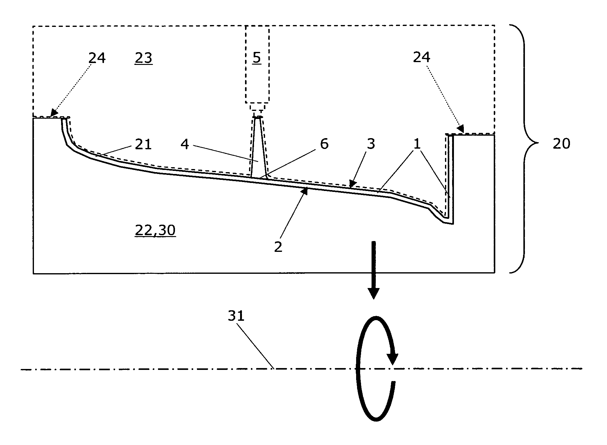
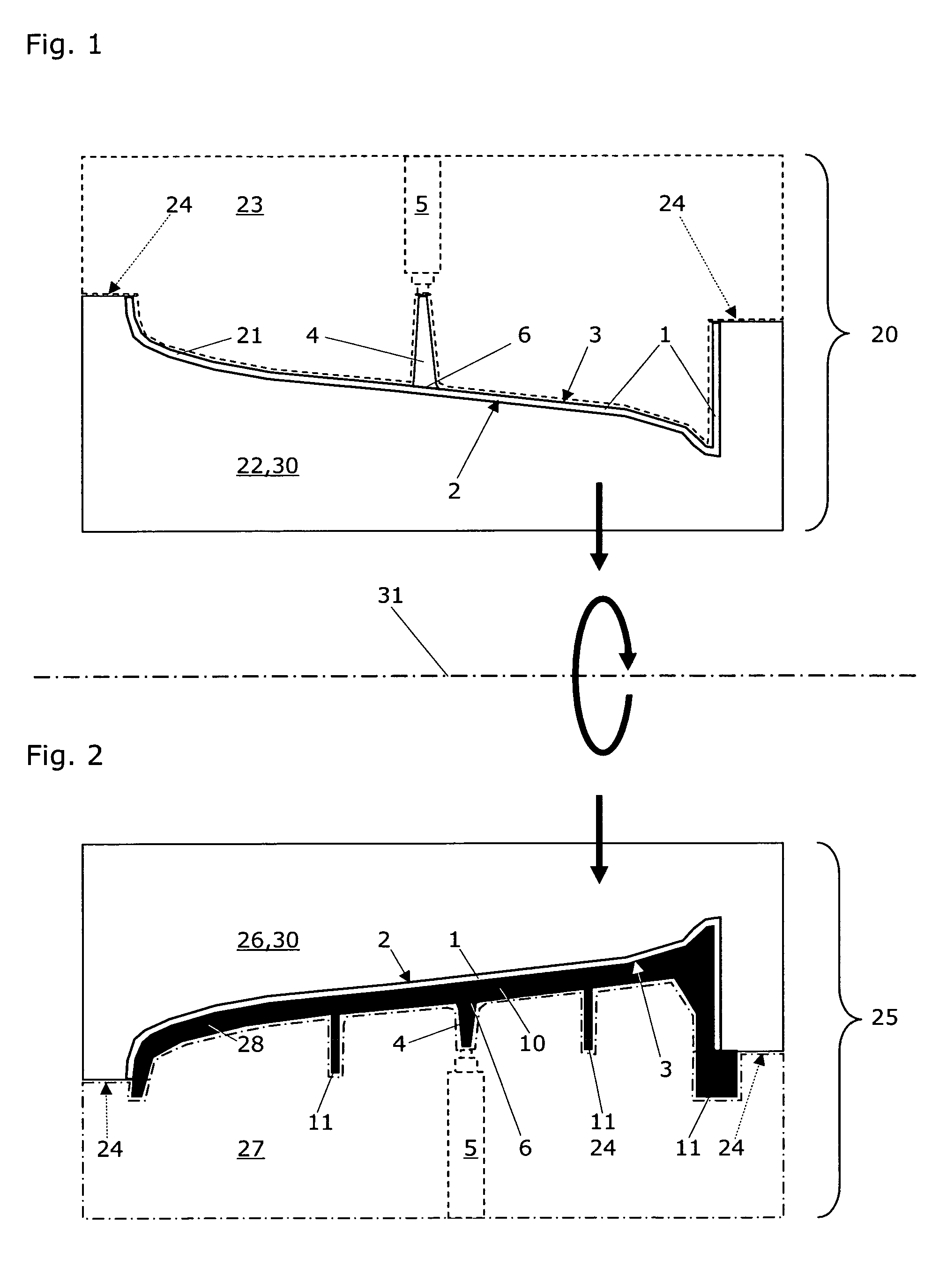
[0022]FIG. 1 shows a section through a closed first injection molding mold to execute the first step of the injection molding method according to the invention for manufacturing plastic parts from thermoplastically processible plastic molding materials.

[0023] Said molding materials, known per se from the prior art, are processed into a plastic part that comprises at least one exposed part 1 and at least one functional part 10, whereby the plastic molding material for the exposed part 1 comprises a transparent or translucent matrix with added effect pigments. The effect dye particles or effect pigments are premixed as a color concentrate, for example, and dosed as a master batch or liquid dispersion into the feeder of an injection molding screw. Alternatively, before injection molding (e.g. by compounding), an appropriate plastic granulate is produced and applied to the injection molding machine. The functional parts 10 can exhibit physical and / or chemical plastic properties differe...


PUM

PropertyMeasurementUnit
Thicknessaaaaaaaaaa
Adhesion strengthaaaaaaaaaa
Transparencyaaaaaaaaaa

Abstract

Disclosed is an injection molding method for manufacturing plastic parts from thermoplastically processible plastic molding materials with at least one exposed part (1) and at least one functional part (10), whereby the plastic molding material for the exposed part (1) comprises a transparent or translucent matrix with added effect pigments, and whereby the functional parts (10) can exhibit different physical and / or chemical plastic properties to the exposed parts (1). The injection molding method comprises the following steps: a) injection molding and solidification of the plastic molding material of the at least one exposed part (1) with an exposed surface (2) and a core surface (3) facing away from the latter in a first mold (20) with a first cavity (21); b) opening of the first mold (20) along a parting line or plane (24); c) closing of a second mold (25) with the at least one exposed part (1) in a second cavity (28); d) injection molding and solidification of the plastic molding material of the functional part (10) on the core surface (3) of the at least one exposed part (1); and e) opening of the second mold (25) and removal of the part. The injection molding method according to the invention is characterized in that for each exposed part (1)—to prevent irregularities such as flow marks and / or knit lines—a single injection nozzle (5) positioned to optimize the flow or at least two injection nozzles in a cascaded injection molding method are used, and that the plastic molding material for the exposed part (1) comprises at least one transparent polymer. The corresponding plastic parts manufactured by injection molding exhibit an exposed surface (2) and a core surface (3) facing away from the latter with at least one injection point (6), whereby the functional part (10) of the plastic part is injection molded onto the core surface (3) of the previously solidified exposed part (1).

Description

RELATED APPLICATIONS [0001] This patent application claims priority of the U.S. Provisional Application No. 60 / 612,639 and of the Swiss patent application No. CH 01563 / 04, both filed on 24, Sep. 2004. The whole content of these two priority applications is incorporated into the present application for all purposes by explicit reference.FIELD OF TECHNOLOGY [0002] The subject of the invention, according to a first aspect and according to the generic term of independent claim 1, is an injection molding method for manufacturing plastic parts from thermoplastically processible plastic molding materials with at least one exposed part and at least one functional part, whereby the plastic molding material for the exposed part comprises a transparent or translucent matrix with added effect pigments, and whereby the functional parts can exhibit different physical and / or chemical plastic properties to the exposed parts. The subject of the invention, according to a second aspect and according t...

Claims


Application Information

Patent Timeline
IPC IPC(8): B29C45/16
CPCB29C45/0013B29C45/16B29C45/1657B29C45/1679B29C45/561B29K2995/0029B29C2045/1682B29K2105/0032B29K2995/002B29K2995/0025B29K2995/0026B29C2045/0032Y10T428/31504B29C45/17B29C45/22
Inventor HALA, RALFKAISSER, MICHAEL
Owner EMS CHEM AG
Learn More