Gas-liquid separator

Active Publication Date: 2006-03-30
YOKOTA SEISAKUSHO
View PDF5 Cites 31 Cited by
  • Summary
  • Abstract
  • Description
  • Claims
  • Application Information

AI Technical Summary

Benefits of technology

[0024] the impeller may be provided with a baffle member which prevents the direct penetration of liquid near the rotating shaft to the exhaust outlet;

Problems solved by technology

Of the above systems, the heating and decompressing types are mainly for batch processing, and are inappropriate for continuous processing, and they are of further disadvantage due to the larger space requirements.
For the permeation membrane type system, clogging of the membrane occurs easily as a result of particles or solids in the liquid and entails increased replacement costs.
However, since the separation is performed only based on the mass difference between the gas and liquid, the separation performance may be outperformed by the suction power of the vacuum means if the enhanced power vacuum means is installed, which may cause liquid penetration into the vacuum means.
Therefore the problem with the centrifugation system is how to achieve strong separation and removal of the gas only.
Therefore it is extremely practical and useful, however, the following problems still remain unsolved in some applications.
Firstly, there remains the problem of insufficient gas-liquid separation performance when the system is applied to advanced defoaming or degassing operations.
Systems referred to as promoting gas-liquid separation, especially the separation and discharge of dissolved gas in the liquid, include systems employing an orifice in the pumped liquid passage for decompressing or increasing the liquid temperature, however, the problem is how to completely capture the separated gas and separate it from the pumped liquid.
Furthermore, in the apparatus of Original Invention 1, centrifugal force for gas-liquid separation is generally produced by the main pump impeller 52 rotation, however, because a powerful vortex and turbulent flow are produced at the same time, some gas cannot be separated centrifugally, which may bleed out to a main pump discharge outlet 51b and cause insufficient gas-liquid separation.
Secondly, in applications for treatment of food and ultra-pure liquid, there is the problem of insufficient cleanability, either when the cleaning system is CIP (Cleaning In Place) or COP (Cleaning Out Place).
However, the structure of Original Invention 1 is complicated due to multiple impellers 52 and 55, multiple chambers across the spacer 53, and many casing members, which means disassembly is difficult.
CIP (Cleaning In Place) of wet areas without leaving any shadows is also difficult due to the complicated passages.
For Original Invention 2, however, the aforementioned second problem, that is the insufficient cleanability of the system, has not been resolved in any way.
The system is not applicable to various kinds of liquids because there is the possibility of clogging due to the bottleneck if particles or masses are mixed in the liquid such as food material.
And, furthermore, if the formed cavity becomes unstable, the mixing of pumped liquid cannot be prevented in the gas-liquid separator because the cavity is simply drawn into the exhaust pipe 76 opening, and therefore, subsequent problems such as the elimination of the mixed liquid require the separate installation of the protection means 78.
These problems are caused inevitably due to the structure of Original Invention 2, and from a technical perspective pose difficulty in solving.
Foremost, if gas-liquid separation performance improvement is the main focus, the structural composition becomes complicated, with the trade-off being insufficient cleanability.
Therefore, resolving the aforementioned two problems, that is “gas-liquid separation performance” and “ease of cleaning” at the same time seemed a difficult challenge.

Method used


Image

  • Gas-liquid separator
  • Gas-liquid separator
  • Gas-liquid separator

Examples


first embodiment

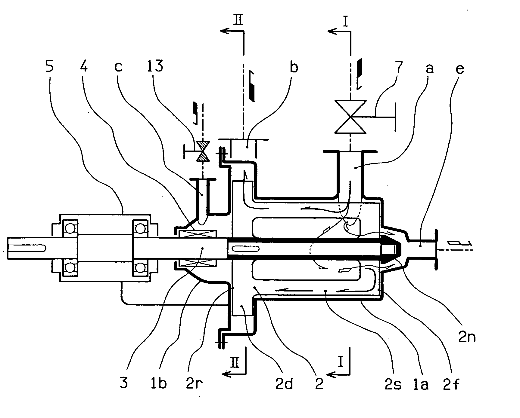
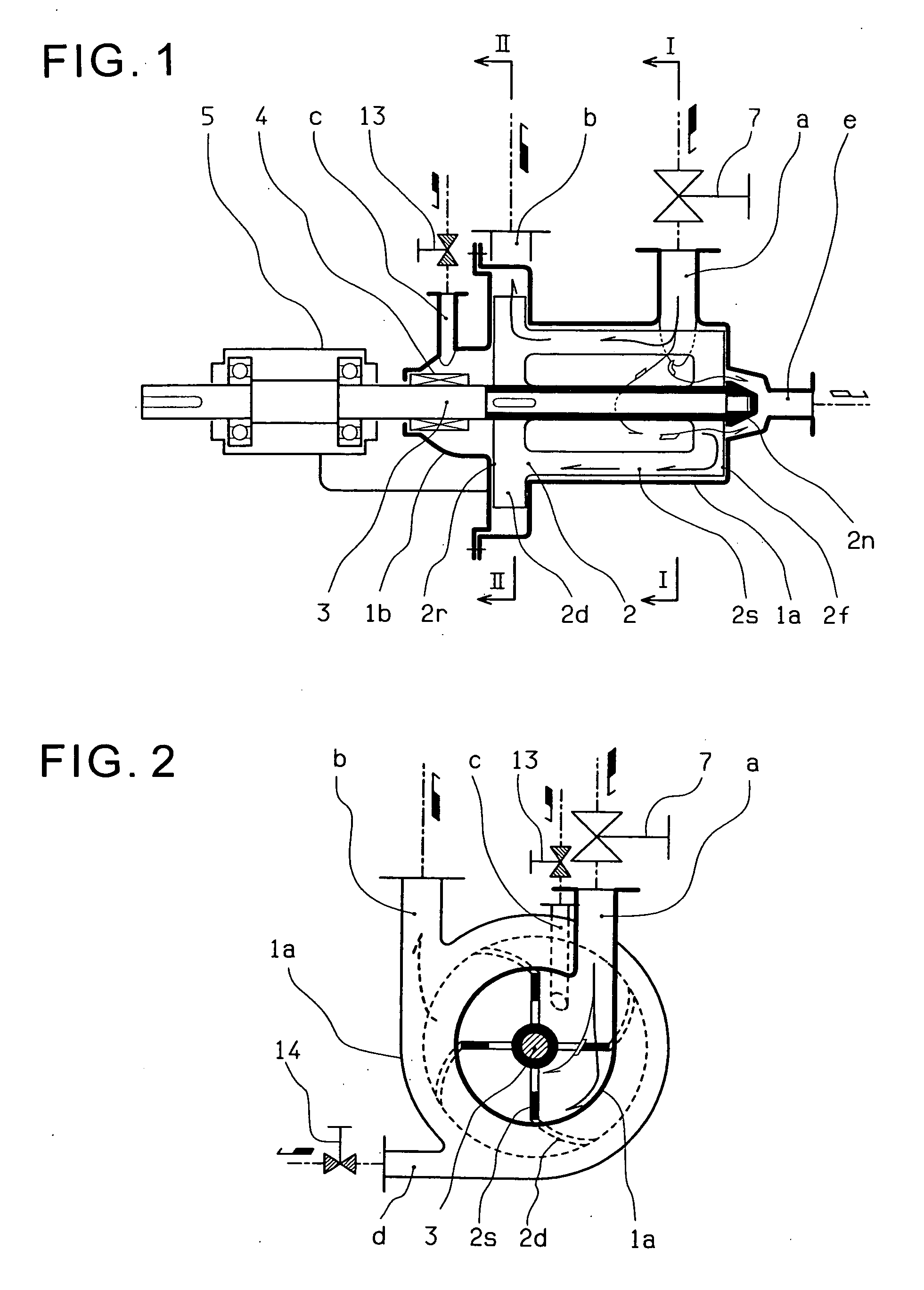
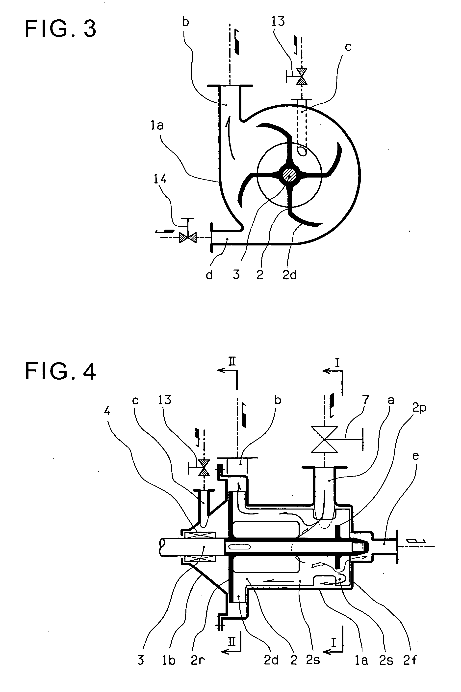
[0049]FIG. 1 shows the present invention, FIG. 2 shows cross-section I-I in FIG. 1, and FIG. 3 shows cross-section II-II in FIG. 1. A casing can be separated into 1a and 1b which form one cylindrical chamber when connected, and an impeller 2 with a suitable number of vanes is disposed in the casing 1a and 1b. The impeller 2, with an outer diameter that allows for a small clearance with respect to the inner wall of the casing 1a, is mounted to a rotating shaft 3. Although it may be mounted by screwing, it is mounted with an impeller nut 2n as illustrated in this embodiment. The rotating shaft 3 is supported by a shaft bearing 5, and penetrates the casing 1b with tight sealing at a shaft sealing 4, and a motor, not shown in the figure, drives the rotation.

[0050] The impeller 2 is provided with a separation impeller part 2s which performs gas-liquid separation in all areas around the rotating peripheral area, and the diameter near the one axial end (the left end in FIG. 1) 2r is expand...

second embodiment

[0070] The rest constitution and functions are the same as those of the

[0071]FIG. 9 illustrates the fourth embodiment and FIG. 10 illustrates section I-I in FIG. 9. In this embodiment, in regard to the impeller 2 in the apparatus of the third embodiment, a cylindrical member 2c, coaxial with the impeller 2, is attached to the impeller 2 at a position opposite the area between the suction inlet a and the discharge outlet b of the casing 1a.

[0072] Due to this structure, the pumped liquid flowing in from the suction inlet a is pushed against the inner wall of the rotating cylindrical member 2c and the rotation force is given from the inner wall simultaneously by flow resistance to separate the gas by centrifugal force, and it is then pushed out of the discharge outlet b by the discharge impeller part 2d. In other words, gas-liquid separation is performed moderately without excessive agitation, fracturing, or shear by friction with the edge of the impeller 2 or the inner periphery of t...

third embodiment

[0074] The rest constitution and functions are the same as those of the

[0075] The fifth embodiment in FIG. 11 shows the cylindrical member 2c of the fourth embodiment installed in multiple rows. Due to this, gas can be suctioned more effectively by increasing the boundary area (the surface area on which the liquid is exposed to the negative pressure of the vacuum means) of the liquid and the gas for gas-liquid separation. The cylindrical members are shown in two rows (2c and 2c′), however, the number of rows may be increased. A means of increasing the boundary area (processing or attaching material for porosity and roughness) may also be devised on these cylindrical members.


PUM

PropertyMeasurementUnit
Centrifugal forceaaaaaaaaaa
Flow rateaaaaaaaaaa

Abstract

The present invention provides a gas-liquid separator with enhanced performance and easy operation, enabling to perform gas-liquid separation such as advanced defoaming or degassing, and facilitating easy cleaning with CIP (Cleaning In Place) and COP (Cleaning Out Place) ability that meets sanitary specifications. This gas-liquid separator for gas-liquid separation performed by centrifugal force of an impeller mounted on a shaft which rotates in a casing comprises: a discharge impeller part providing discharge force to the passing fluid formed on an axial end of the impeller; a discharge outlet of the casing disposed in a position opposite the discharge impeller part; the other axial end of the impeller being formed to slide on the inner wall of the casing; an exhaust outlet of the casing disposed in a position opposite the sliding impeller part; vacuum means connected to the exhaust outlet; and a suction inlet of the casing disposed in a position between the discharge outlet and the exhaust outlet.

Description

BACKGROUND OF THE INVENTION [0001] 1. Field of the Invention [0002] The present invention relates to a gas-liquid separator which performs advanced gas-liquid separation such as defoaming or degassing, and is easy to clean or disassemble meeting sanitary specifications. [0003] 2. Description of the Prior Art [0004] Generally known systems referred to as gas-liquid separators for defoaming and degassing include container type devices that are filled with liquid and then heated or decompressed, systems that employ a gas permeation membrane where only the gas can pass, and systems employing centrifugation. [0005] Of the above systems, the heating and decompressing types are mainly for batch processing, and are inappropriate for continuous processing, and they are of further disadvantage due to the larger space requirements. For the permeation membrane type system, clogging of the membrane occurs easily as a result of particles or solids in the liquid and entails increased replacement c...

Claims


Application Information

Patent Timeline
IPC IPC(8): B01D45/00B01D19/00
CPCB01D19/0052
Inventor YOKOTA, HIROSHINISHI, FUMIO
Owner YOKOTA SEISAKUSHO
Why Eureka
Try Eureka