
Air conditioner system

A technology of air-conditioning systems and throttling components, applied in lighting and heating equipment, compressors with reversible cycles, fluid circulation arrangements, etc., can solve the problem of reducing the heat exchange efficiency of the evaporator, insufficient separation of gas and liquid, and optimal efficiency and other issues to achieve the effect of improving energy utilization efficiency, optimizing cooling efficiency, and optimizing heating efficiency

Pending Publication Date: 2020-04-07
GUANGDONG MEIZHI PRECISION MFG
View PDF0 Cites 5 Cited by
  • Summary
  • Abstract
  • Description
  • Claims
  • Application Information

AI Technical Summary

Problems solved by technology

The inlet and liquid outlet of the two-way flash evaporator are usually arranged symmetrically at the bottom of the flash evaporator, while the gas outlet is arranged on the top of the flash evaporator. The flash evaporator with this structure usually has the disadvantage of high liquid level when it works, and it is easy to make the gaseous state The liquid is entrained at the outlet, and after spraying into the compressor, it is easy to cause liquid shock in the compressor; at the same time, the separation of gas and liquid in the flash is not sufficient, and it is easy to mix gas at the liquid outlet, reducing the heat exchange efficiency of the evaporator
In addition, because the refrigerant flow direction of the two-way flash evaporator is different during cooling and heating, and the mass flow rate of refrigerant required for cooling and heating is not exactly the same, so it is easy to appear that the working liquid level of the flash evaporator during cooling and heating In the case of inconsistency, the most efficient flash evaporator for cooling may not be the most efficient for heating

Method used


Image

  • Air conditioner system
  • Air conditioner system
  • Air conditioner system

Examples


Embodiment Construction

[0046] In order to understand the above-mentioned purpose, features and advantages of the present invention more clearly, the present invention will be further described in detail below in conjunction with the accompanying drawings and specific embodiments. It should be noted that, in the case of no conflict, the embodiments of the present application and the features in the embodiments can be combined with each other.

[0047] In the following description, many specific details are set forth in order to fully understand the present invention. However, the present invention can also be implemented in other ways than described here. Therefore, the protection scope of the present invention is not limited by the specific implementation disclosed below. Example limitations.

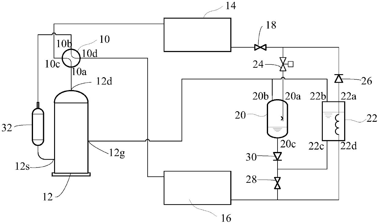
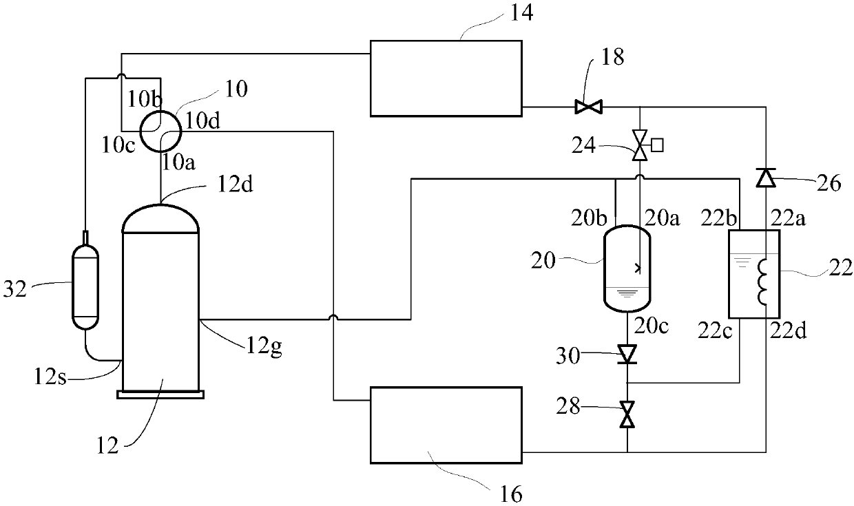
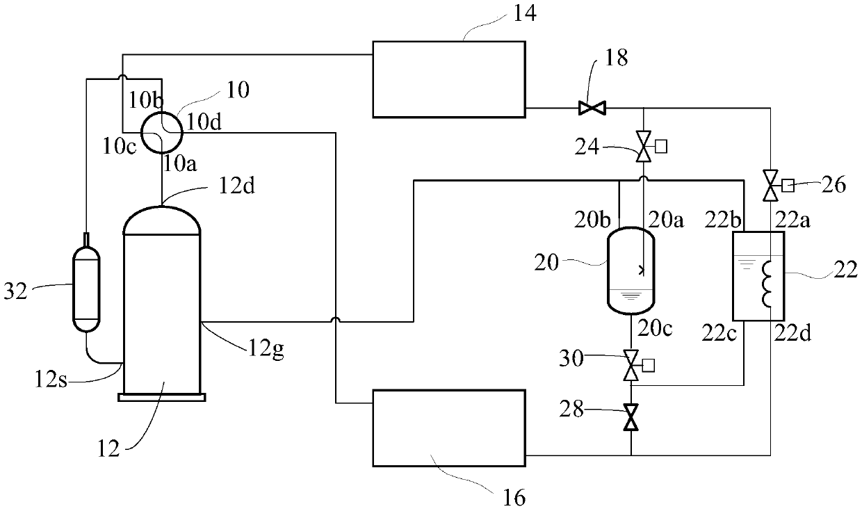
[0048] Refer below Figure 1 to Figure 4 The air conditioning system provided according to one embodiment of the present invention will be described.

[0049] Such as Figure 1 to Figure 4 As shown, an air...


PUM


Abstract

The invention provides an air conditioner system which comprises a reversing assembly, an indoor heat exchanger and an outdoor heat exchanger. The air conditioner system further comprises a compressor, a first throttling element, a flash evaporator and an economizer. The compressor comprises an exhaust port, an intermediate air injection port and an air suction port; the first throttling element is arranged between the indoor heat exchanger and the outdoor heat exchanger; the flash evaporator is arranged between the first throttling element and the outdoor heat exchanger and comprises a refrigerant inlet, an air outlet and a liquid outlet, the refrigerant inlet is connected with the first throttling element, and the liquid outlet is connected with the outdoor heat exchanger; the economizeris arranged in parallel with the flash evaporator and comprises a first pipe port, a second pipe port, a third pipe port and a fourth pipe port, the first pipe port is connected with the first throttling element, the second pipe port and the air outlet are both connected with the middle air injection port, and the third pipe port and the fourth pipe port are connected with the outdoor heat exchanger. When in the refrigerating mode and the heating mode, the flash evaporator or the economizer can be selected respectively, so that the refrigerating efficiency and the heating efficiency of the air conditioner system can be optimized respectively, and the annual energy utilization efficiency is improved.

Description

technical field [0001] The present invention relates to the technical field of refrigeration, and more specifically, to an air conditioning system. Background technique [0002] Currently existing air conditioning systems with flash evaporators or economizers often only use one of the flash evaporators or economizers. For an air conditioning system that only uses a flash evaporator, in order to take into account both cooling and heating modes, a bidirectional flash evaporator is often used. The inlet and liquid outlet of the two-way flash evaporator are usually symmetrically arranged at the bottom of the flash evaporator, while the gas outlet is arranged at the top of the flash evaporator. The flash evaporator with this structure usually has the disadvantage of high liquid level when it works, and it is easy to make the gaseous state The liquid is entrained at the outlet, and after spraying into the compressor, it is easy to cause liquid shock in the compressor; at the same...

Claims


Application Information

Patent Timeline
IPC IPC(8): F25B13/00F25B41/04F25B41/00F25B41/20F25B41/40
CPCF25B13/00F25B2400/13F25B41/26F25B41/40F25B41/20
Inventor 杨宇飞廖四清王小龙王明然
Owner GUANGDONG MEIZHI PRECISION MFG
Learn More