
Methods, systems, and carrier media for evaluating reticle layout data

a technology of layout data and carrier media, applied in the field of methods, systems and carrier media for evaluating reticle layout data, can solve the problems of direct impact, increased complexity of integrated circuit design, and increased complexity of design of integrated circuits, so as to achieve the effect of successful reticle manufactur

Active Publication Date: 2006-03-23
KLA TENCOR TECH CORP
View PDF99 Cites 161 Cited by
  • Summary
  • Abstract
  • Description
  • Claims
  • Application Information

AI Technical Summary

Benefits of technology

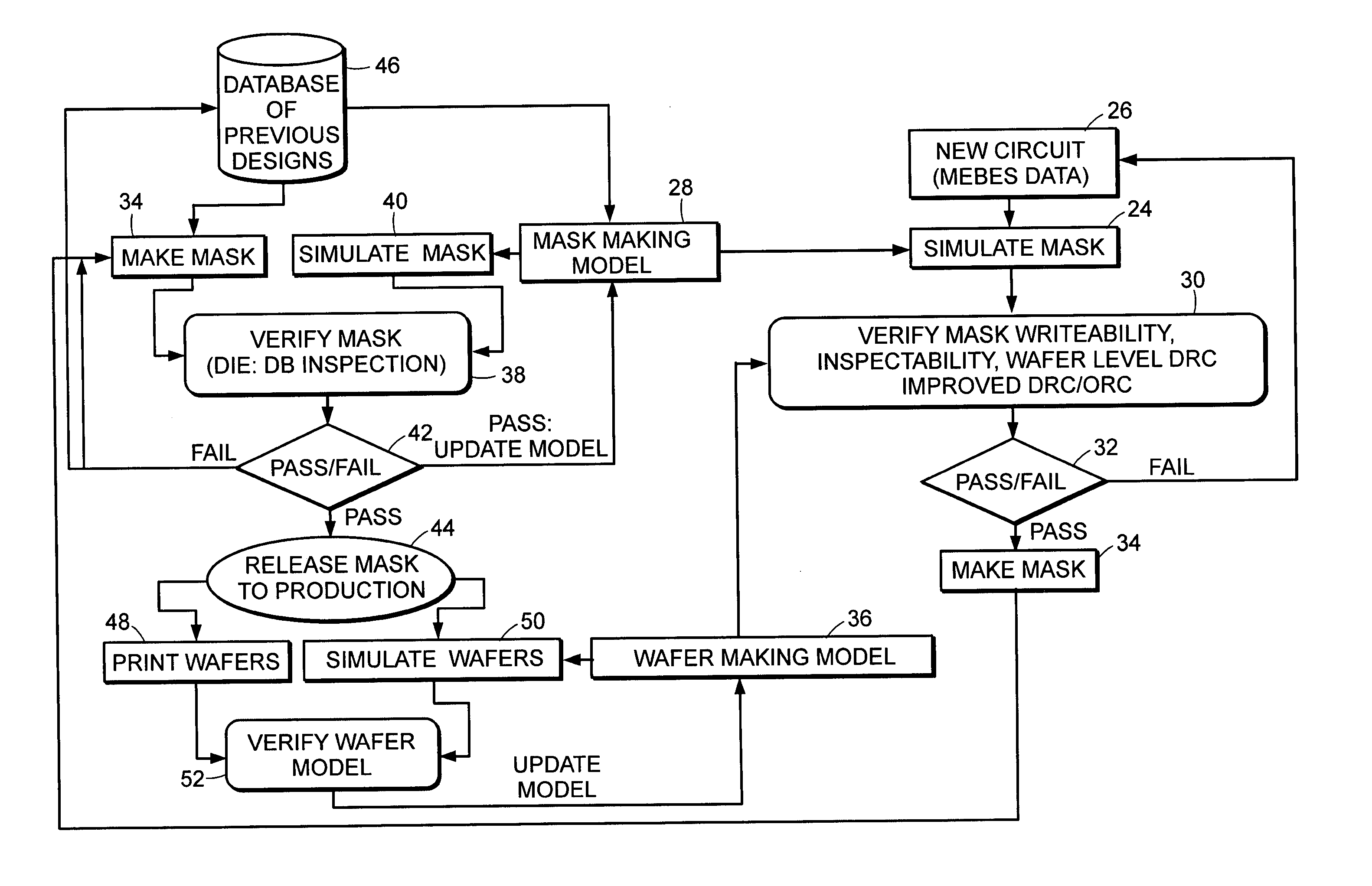
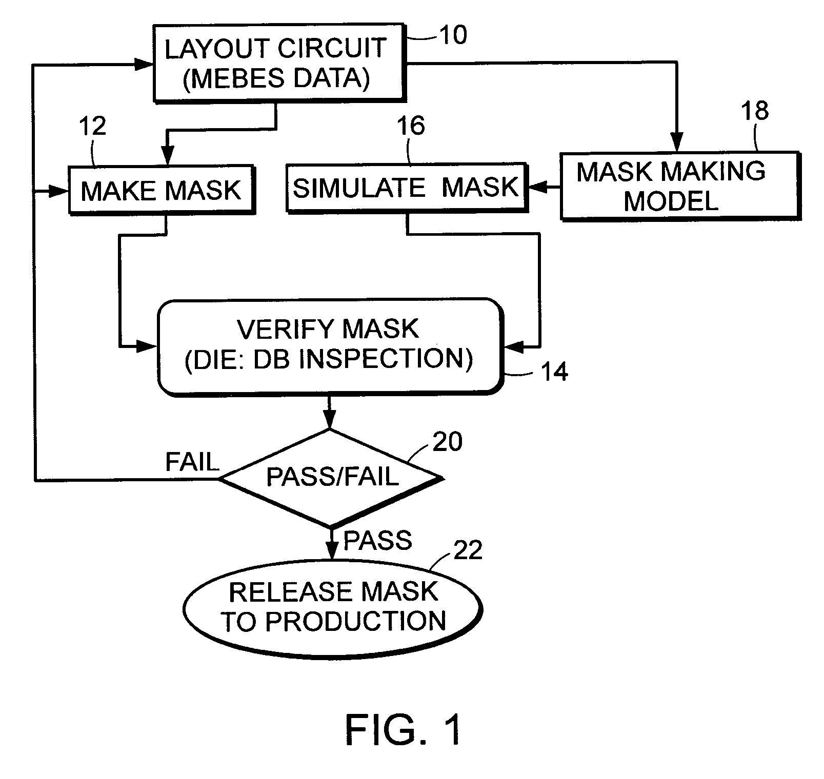
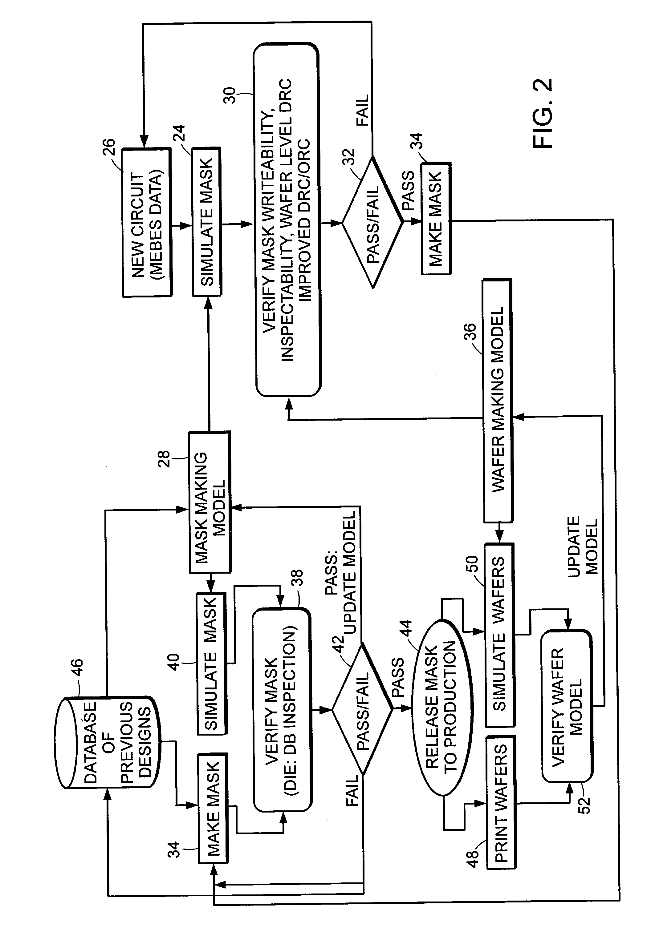
[0022] An embodiment relates to a computer-implemented method for evaluating reticle layout data. The method includes generating a simulated image using the reticle layout data as input to a model of a reticle manufacturing process. The simulated image illustrates how features of the reticle layout data will be formed on a reticle by the reticle manufacturing process. The method also includes determining manufacturability of the reticle layout data using the simulated image. The manufacturability is a measure of how accurately the features will be formed on the reticle.

Problems solved by technology

As integrated circuits become increasingly complex, the design of the integrated circuits also increases in complexity.
The complexity of the integrated circuit design, therefore, has a direct impact on the manufacture and inspection of reticles.
Accordingly, as the complexity of the integrated circuit design increases, successful reticle manufacture becomes more difficult.
In this manner, it becomes more difficult to form these features on a reticle due to, for example, limitations of the reticle manufacturing process.
In a similar manner, it becomes more difficult to inspect these features due to limitations of the reticle inspection processes.
Furthermore, as is known in the art, the difficulty of successfully reproducing these features on wafers increases as the dimensions and spacings decrease.
The OPC features further complicate the design, manufacture, and inspection of the reticle.
Furthermore, optical effects such as mask error enhancement factor (MEEF) may cause additional distortion of the final image at the wafer level.
While this and other methods known in the art for correcting design rule violations in a mask layout file have proven to be somewhat successful, DRC and ORC systems currently in use suffer from several limitations.
These process biases may alter some of the features included in the design, especially sub-resolution OPC structures such as scattering bars, serifs, or small edge extensions such that they become so small that they disappear from the data entirely or become large enough to cause problems such as bridging in either the reticle or wafer printing process.
In a further example, the list of design rules becomes impractically long as processes become more complex.
Encoding the design rules into software and ensuring that they completely encompass all possible patterning errors that will reduce device yield is increasingly difficult.
If the design rule developer fails to anticipate every possible violation that would impact device performance, these violations will pass through the DRC system undetected.
DRC and ORC simulations also do not capture the details of the mask making process and offer no means of calibrating the patterns to reflect what will actually be written on the reticle.
For example, the current state of the art integrated circuit designs can produce complex designs and layouts that pass the current rule checks, but cannot be manufactured either because the RET pattern is too complex to be written correctly on the reticle, inspected on the reticle, and / or printed at the wafer level.
However, once the OPC structures are added, numerous design rule violations are still possible.
Therefore, the existing rule checkers act on idealized data without addressing the key question of whether or not the design can be written and inspected to yield a manufacturable process from design to reticle to wafer levels.
Many design databases take the initial physical design and add incredibly complex RETs which expand the design data by more than an order of magnitude.
The resulting large data files lead to very long and expensive reticle writing times which are basically wasted since the pattern cannot be reproduced with all of the tiny CD variations and sub-resolution jogs.
In yet another example, the currently available DRC and ORC systems do not take into account whether or not the pattern can be adequately inspected.
For example, even if the patterns could be written, no inspection tool is available that is capable of verifying the correct writing of such patterns and no exposure tool is believed to be available that could print such patterns.
Therefore, the effort is wasted.
Some of the small RET implementations may actually be counterproductive since in trying to write them on the reticle only a partial pattern can be defined, which can end up creating defects on the reticle and later on the wafer.
Writing such large data files on a reticle is relatively expensive.

Method used


Image

  • Methods, systems, and carrier media for evaluating reticle layout data
  • Methods, systems, and carrier media for evaluating reticle layout data
  • Methods, systems, and carrier media for evaluating reticle layout data

Examples


Embodiment Construction

[0037] The terms “reticle” and “mask” are used interchangeably herein. A reticle generally includes a transparent substrate such as glass, borosilicate glass, and fused silica having opaque regions formed thereon in a pattern. The opaque regions may be replaced by regions etched into the transparent substrate. Many different types of reticles are known in the art, and the term reticle as used herein is intended to encompass all types of reticles.

[0038] A process for manufacturing a reticle is similar to a wafer patterning process. For example, the goal of reticle manufacturing is generally to form a pattern in an opaque material such as a relatively thin chrome layer on a substantially transparent substrate such as glass. In addition, other appropriate opaque materials that may be used for reticle manufacturing include, but are not limited to, chromium, chromium oxide, chromium nitride, and molybdenum / silicon. Appropriate thicknesses for chrome layers may be approximately 1000 Å an...


PUM


Abstract

Various computer-implemented methods are provided. One method for evaluating reticle layout data includes generating a simulated image using the reticle layout data as input to a model of a reticle manufacturing process. The simulated image illustrates how features of the reticle layout data will be formed on a reticle by the reticle manufacturing process. The method also includes determining manufacturability of the reticle layout data using the simulated image. The manufacturability is a measure of how accurately the features will be formed on the reticle. Also provided are various carrier media that include program instructions executable on a computer system for performing a method for evaluating reticle layout data as described herein. In addition, systems configured to evaluate reticle layout data are provided. The systems include a computer system and a carrier medium that includes program instructions executable on the computer system for performing method(s) described herein.

Description

PRIORITY CLAIM [0001] This application claims priority to U.S. Provisional Application No. 60 / 609,670 entitled “Methods, Systems, and Carrier Media for Evaluating Reticle Layout Data,” filed Sep. 14, 2004, which is incorporated by reference as if fully set forth herein.BACKGROUND OF THE INVENTION [0002] 1. Field of the Invention [0003] The present invention generally relates to methods, systems, and carrier media for evaluating reticle layout data. Certain embodiments relate to a computer-implemented method that includes determining manufacturability, inspectability, and / or printability of reticle layout data. [0004] 2. Description of the Related Art [0005] The following description and examples are not admitted to be prior art by virtue of their inclusion in this section. [0006] Designing an integrated circuit involves creating a schematic design that includes individual devices arranged and coupled to perform a particular function. As integrated circuits become increasingly comple...

Claims


Application Information

Patent Timeline
IPC IPC(8): G06F17/50G06K9/00G03F1/36G03F1/68G03F1/70
CPCG06F17/5068G03F1/36G06F30/39
Inventor VERMA, GAURAVGLASSER, LANCEPREIL, MOSHE E.
Owner KLA TENCOR TECH CORP
Learn More