
Method and apparatus for extruding cementitious articles

a cementitious article and extruder technology, applied in the direction of shaping presses, solid waste management, sustainable waste treatment, etc., can solve the problems of reduced commercial viability, uncontrollable backflow of material, and high pressure at the die, so as to reduce the amount of uncontrollable backflow and reduce the clean-up time

Inactive Publication Date: 2006-03-23
CHEN HONG +3
View PDF21 Cites 24 Cited by
  • Summary
  • Abstract
  • Description
  • Claims
  • Application Information

AI Technical Summary

Benefits of technology

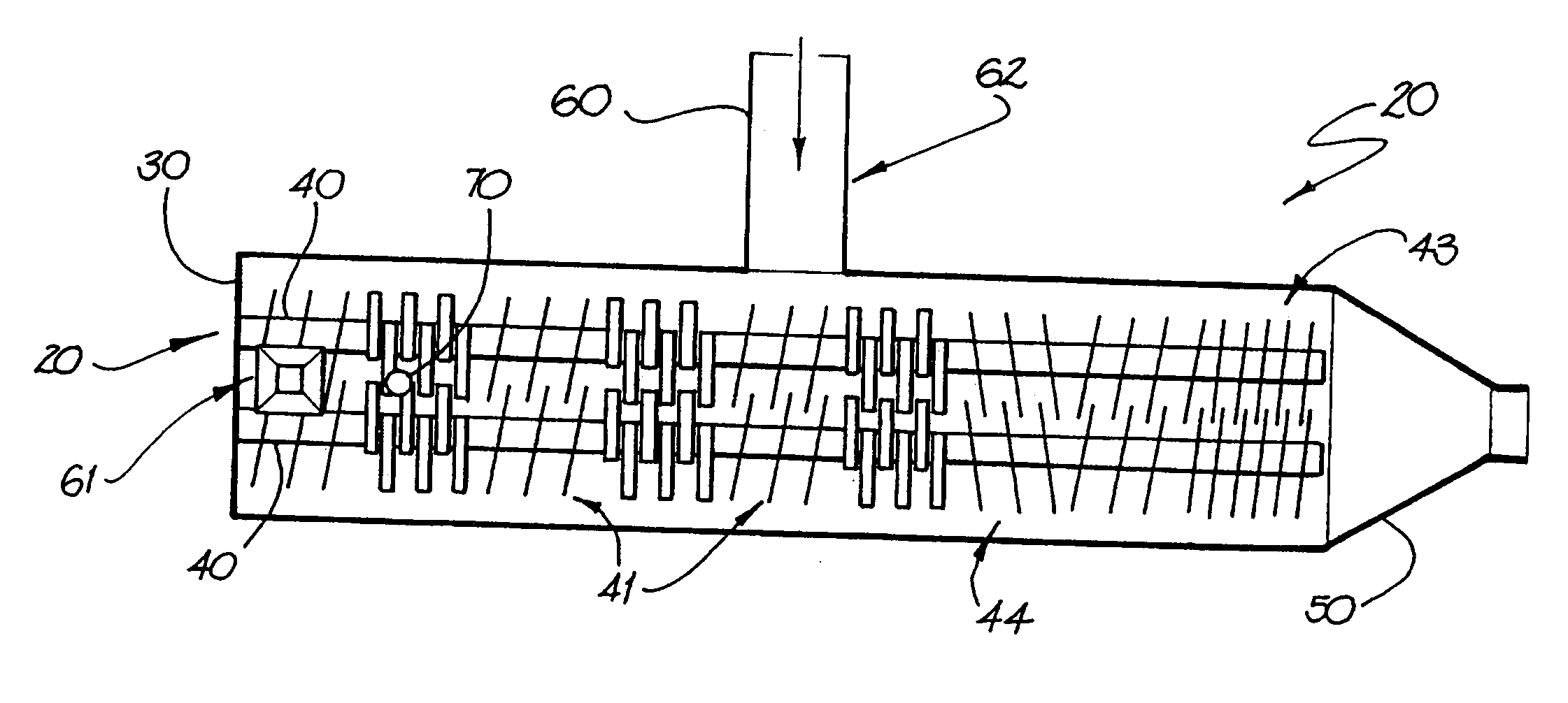
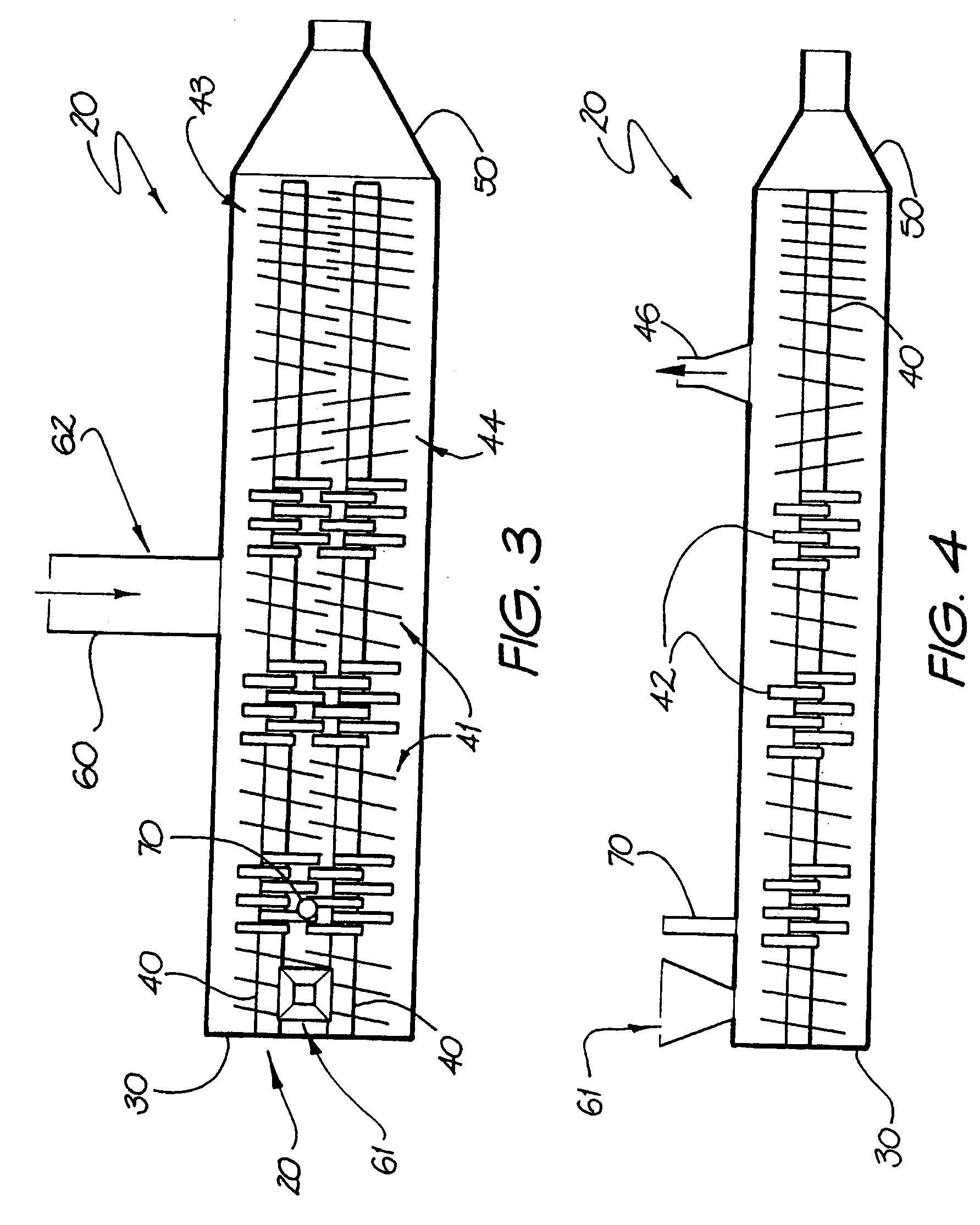
[0027] The applicant has surprisingly found that a particular type of extruder used in the polymer industry is suitable for continuous extrusion of fibre reinforced cement. There are many designs of extrusion machine in the polymer industry which can be fed with many different ingredients directly into the feed section of the extruder. A specific type of polymer extruder is the so-called “self wiping twin screw” (SWTS) extruder. This extruder comprises two screws rotatably mounted in a casing including two parallel cylindrical intersecting bores. The screws are in mesh so that the material to be processed is subjected to a powerful field of shear forces. An example of such a SWTS extruder is disclosed in U.S. Pat. No. 3,883,122. This type of machine is particularly efficient because the intermeshing of the screws provides a self-wiping action which minimises the amount of uncontrolled backflow of substance being pumped. This self-wiping action also acts to clean the interior of the casing thereby reducing clean-up time.
[0028] It is this SWTS type extruder which the applicant has most surprisingly found to be not only suitable for extrusion of fibre cement but provide significant advantages over conventional production techniques as will be discussed below.

Problems solved by technology

Extrusion of fibre cement products has been performed on a limited basis but it has a number of difficulties which have reduced its commercial viability.
The material can be subjected to high pressures at the die.
This batch-type process is obviously quite inefficient.
There are many reasons why, to date, no continuous high speed extrusion machines have been used, or indeed, suspected as being suitable for extruding fibre cement including the difficulty with controlled feeding of fiberised cellulose, the high temperatures generated by the speeds and torques generated by these machines, the high intensity localised shearing, the highly abrasive nature of the cementitious, siliceous and other such materials common in the building industry, and the high capital cost of these extrusion machines.
Further, as is well-known in the art, the use of asbestos fibres is outlawed in many countries and is undesirable even in those countries where its use is legal.
Synthetic fibres have been considered and are commonly used; however, they are expensive and some are unable to be cured at high temperatures such as in an autoclave.
However, cellulose fibres are difficult to disperse and extrude, and often require the use of powerful process aids.
Fibres that are clumped or matted together cause localised variations in product properties and are deleterious to overall performance.
As this light and fluffy material is difficult to handle and compacts on storage, it is often produced immediately before use.
The use of fiberised pulp, and the use of hammermills is associated with noise control, dust control, explosion control, and other expensive issues.
Furthermore, the form of the fiberised cellulose is not such that can be easily pumped or conveyed, and accurate continuous feeding is extremely difficult.
Efforts have been made to overcome this issue by pelletising the cellulose (e.g., Cellulose Filler Factory makes a product called ‘Topcel’), but these pellets are only 75% cellulose and contain a large amount of undesirable contaminants.
Moreover, the fibres are extremely short and weak, and not the kind useful for providing good reinforcement.
With regard to the high temperatures generated by the conventional extrusion processes, a problem arises with the process aids used to plasticise the fibre cement.
It is often the case that these process aids significantly increase the cost of the extruded product.
The high rotational screw speed used in the continuous extruders, combined with the narrow clearances can cause considerably more temperature rise in the substance being extruded than is encountered in the use of conventional fibre cement extruders.
Thus, it was believed that the use of continuous extruders may not be compatible with the commonly used process aids for fibre-cement.
Too high a temperature rise may dry out the product, removing water essential for cement hydration.
Further, the thermal acceleration of the cement setting reaction may cause complications in controlling the process control (as well as from a maintenance) point of view.
Continuous extruders also cause difficulties with the use of density modifiers.
Many of these additives are highly porous and structurally fragile.
Though their structure remains intact during the mixing and kneading stages of conventional fibre cement manufacture, high speed continuous extrusion machines are generally built with very small clearances and induce very large amounts of localised shear.
This process damages the structure of these density modifying fillers, pulverising them and increasing their density, thus lowering their efficacy as density modifiers.
Very small clearances and rapid rotations of the screws give rise to high wear.
Though various metal treatments and coatings are available to improve the wear resistance of the extruder, fibre cement paste is, by nature, more abrasive than the materials they are designed for.
Given the high cost of the extruder and its replacement components, this is a deterrent to its use in the low margin fibre cement industry.

Method used


Image

  • Method and apparatus for extruding cementitious articles
  • Method and apparatus for extruding cementitious articles
  • Method and apparatus for extruding cementitious articles

Examples


Embodiment Construction

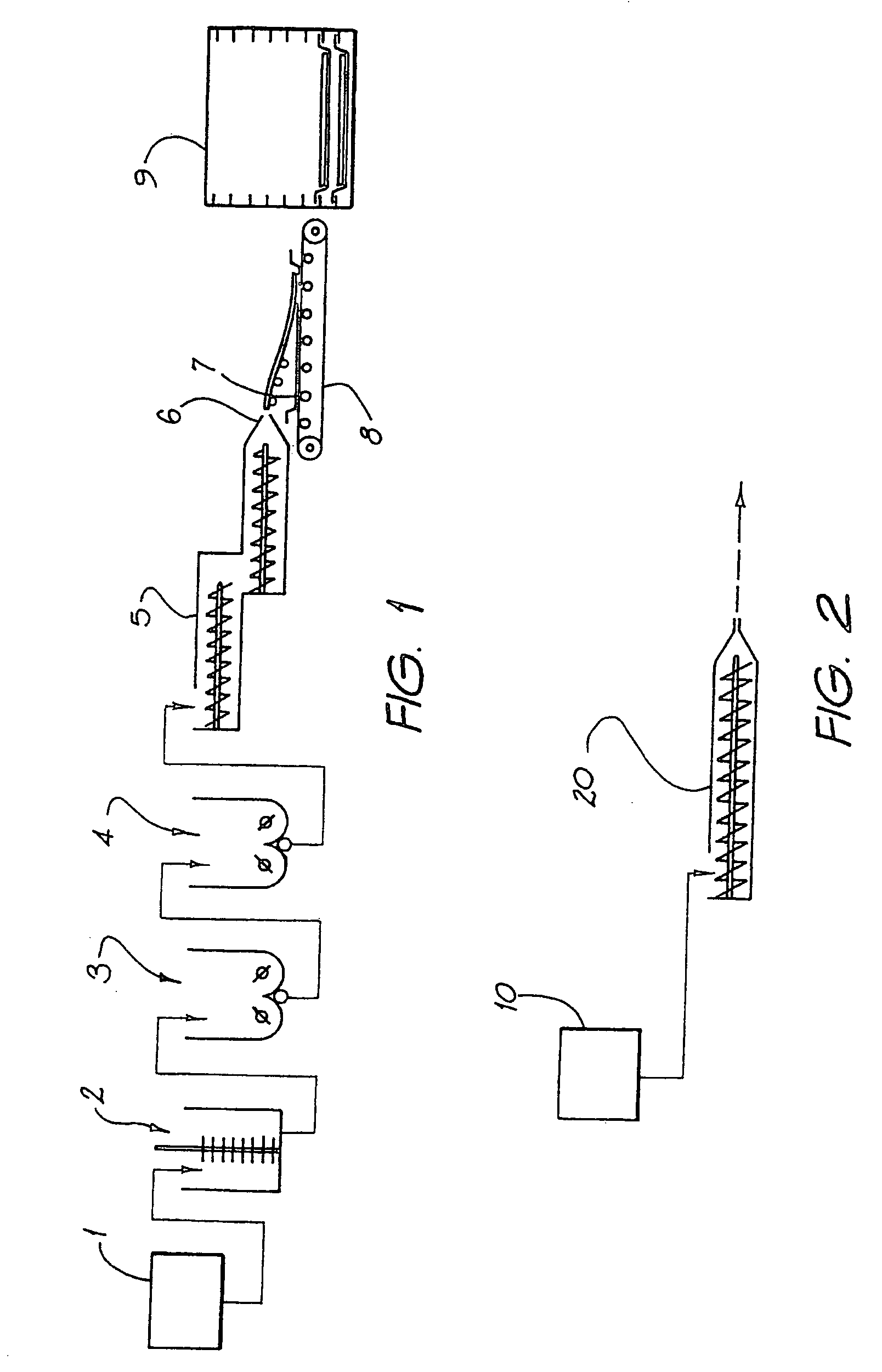
[0032] Turning firstly to FIG. 1, a brief explanation of the conventional fibre cement extrusion process will assist in recognising the unique characteristics of the new process and apparatus.

[0033] In FIG. 1, the various components of the fibre cement are provided to a weighing plant 1. This weighing plant provides the precise quantities of the various components to a mixer 2, where they are dry and / or wet mixed to the desired homogeneity and consistency. This material is then transferred as a batch to the kneader 30, which kneads the material once again with the optional addition of water. The cementitious solid or paste is then transferred as a batch to a feeder 4. This feeder provides a constant supply of cementitious material to the extruder 5. The entire process up to feeder 4 is a batch-type process.

[0034] The extruder 5 forces the cementitious material through die 6. It should be recognised, however, that the extruder simply compacts and forces the cementitious material th...


PUM

PropertyMeasurementUnit
Fractionaaaaaaaaaa
Fractionaaaaaaaaaa
Fractionaaaaaaaaaa

Abstract

A method and apparatus (20) for extruding fibre cement. The extruder comprises a casing (30) with a pair of inter-meshing self-wiping screws (40) rotatably mounted therein. The screws continuously mix and or knead the components of the fibre cement provided through various feed means (61, 62) to form a substantially homogeneous paste and force the paste through a die (50) to form a green cementitious extrudate suitable for curing.

Description

CROSS-REFERENCE TO RELATED APPLICATIONS [0001] This application is a divisional of U.S. application Ser. No. 10 / 168,240, which is the 35 U.S.C. § 371 filing of Application No. PCT / AU00 / 01551, filed Dec. 15, 2000, which was published as WO 01 / 43931 A1 under PCT Article 21(2) in English.TECHNICAL FIELD [0002] The present invention relates to methods and apparatus for extruding cementitious articles in particular fibre reinforced cement building products. BACKGROUND ART [0003] Fibre reinforced cement boards and other products have been widely used as materials for walls, ceilings, roofs, floors etc., of buildings and for substitutes for wood trim, frames, etc. [0004] There are many methods for forming and shaping such FRC products including Hatschek sheet process, Mazza pipe process, Magnani sheet process, injection moulding, hand lay-up, casting, filter pressing, roll forming, etc. [0005] Extrusion of fibre cement products has been performed on a limited basis but it has a number of d...

Claims


Application Information

Patent Timeline
IPC IPC(8): B29C47/60C04B16/02B28B1/52B28B3/20B28B3/22B28B17/02B28C5/14B28C5/40B29C48/40B30B11/24C04B28/02
CPCB28B1/52B29C47/6056B28B3/224B28B17/02B28C5/146B28C5/40B30B11/243C04B28/02C04B2111/00129B28B3/22B29C47/6037B29C47/6031B29C47/366C04B18/24C04B40/0028B29C48/385B29C48/54B29C48/55B29C48/57B29C48/405B29C48/40Y02W30/91B29B7/483
Inventor CHEN, HONGBURWOOD, RICHARD JOHNMAXWELL, IAN ANDREWGORINGE, NILMINI SUREKA
Owner CHEN HONG
Learn More