
Liquid electrochemical cell stacks and manufacturing methods for same

a technology of liquid electrochemical cells and cassettes, applied in the direction of cell components, sustainable manufacturing/processing, electrolyte stream management, etc., can solve the problems of high cost of fuel cells when compared to conventional power generation technology, deterred their potentially widespread use, and high cost of fabricating and assembling fuel cells, etc., to reduce the cost of these systems

Inactive Publication Date: 2006-03-16
SILICON VALLEY BANK
View PDF6 Cites 32 Cited by
  • Summary
  • Abstract
  • Description
  • Claims
  • Application Information

AI Technical Summary

Benefits of technology

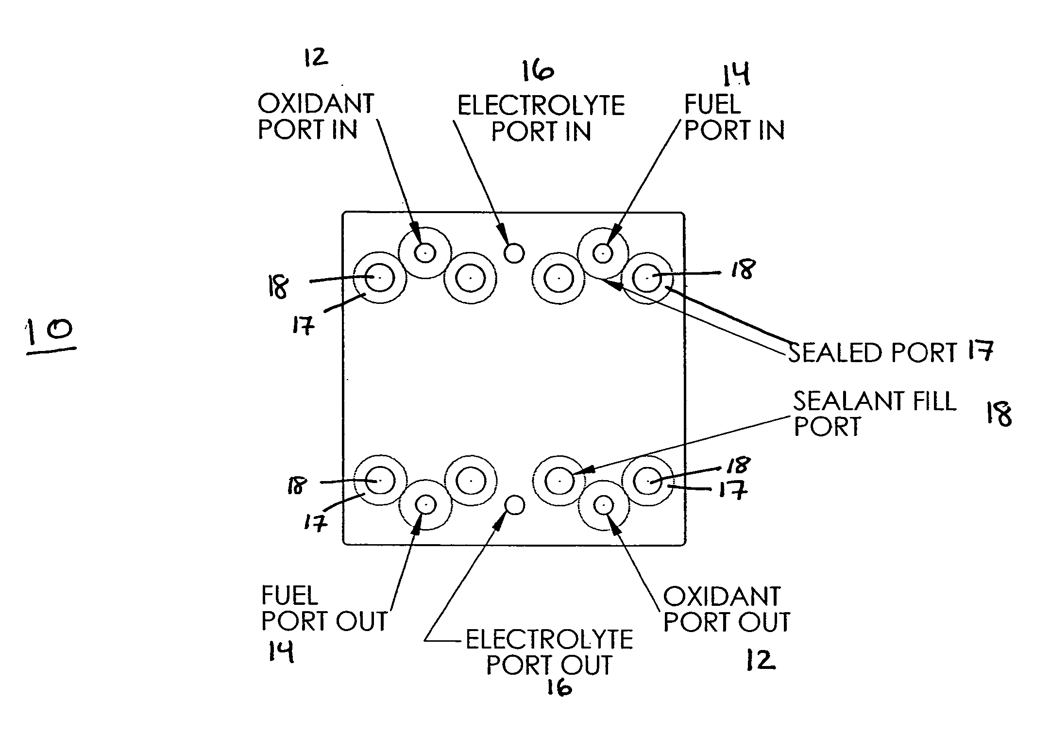
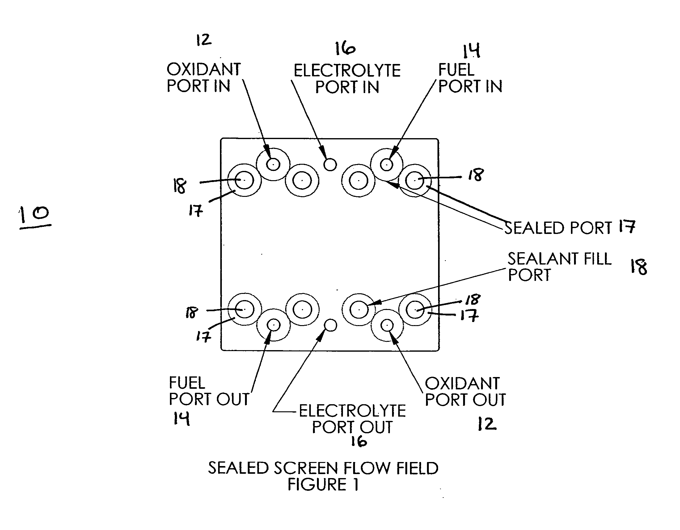
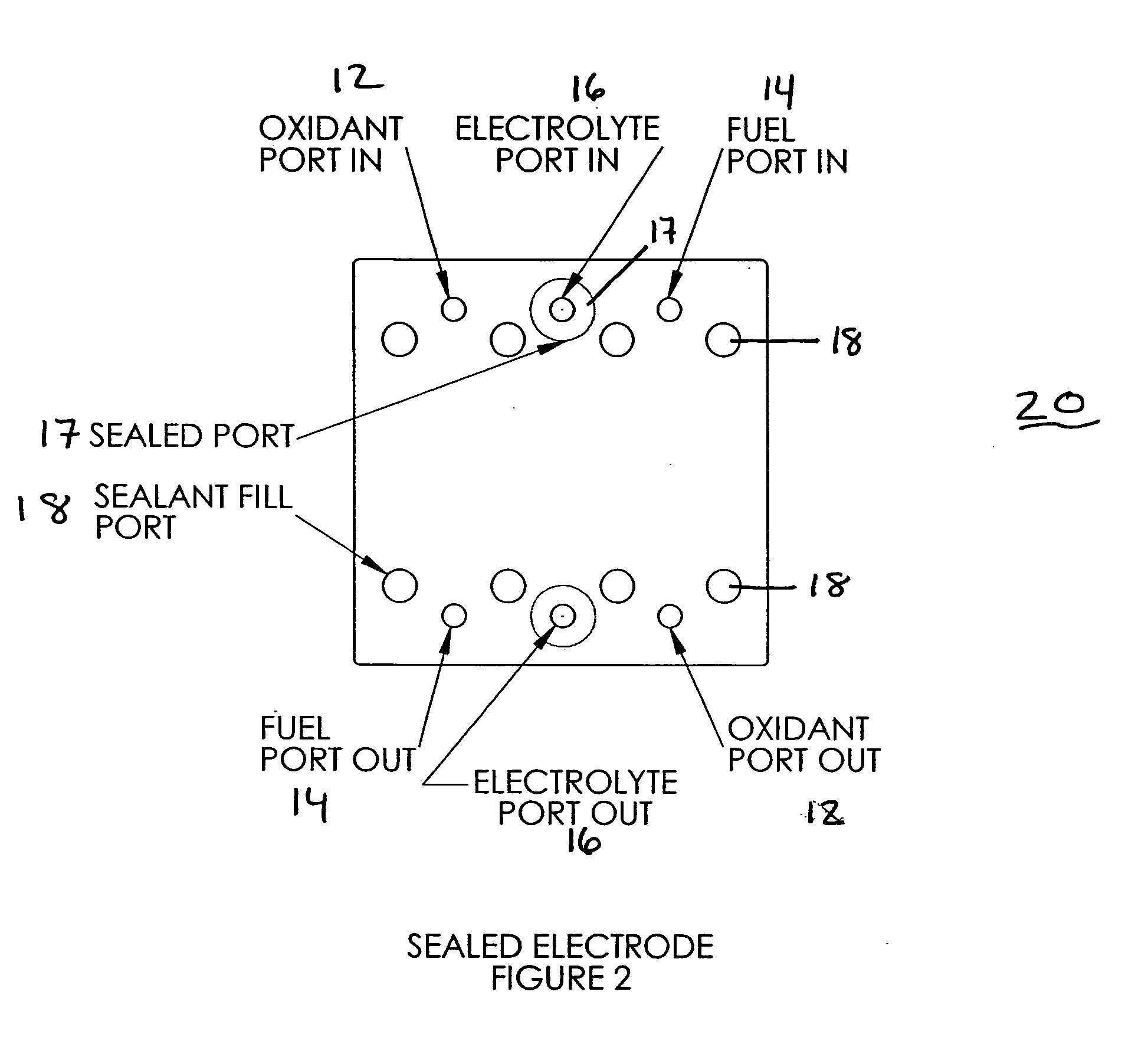
[0016] The fuel cell cassette can be manufactured from the same materials and using the methods as described in World Publications WO 02 / 43173 and WO 03 / 036747, and International Patent Application PCT / US03 / 12684. The basic principle exploited allows for an edge-sealing material to block certain ports while leaving others open, based on the number, shape and placement of holes and channels cut within the flow fields and / or other components. This design and process would be especially useful for the formation of electrochemical cassettes via resin transfer molding or injection molding techniques. Typically, the membrane electrode assembly component of the electrochemical cassettes described in the above referenced patent applications is replaced with two porous electrodes and a liquid electrolyte flow field. As described in those previous patent applications, this innovation allows for the production of fuel cell stacks with a minimum of labor, thereby significantly reducing the cost of these systems.

Problems solved by technology

However, the high cost of fuel cells when compared to conventional power generation technology has deterred their potentially widespread use.
The cost of fabricating and assembling fuel cells can be significant, due to the materials and labor involved, and as much as 85% of a fuel cell's cost can be attributed to manufacturing.
Current applications of liquid electrolyte fuel cells are limited to space and military applications requiring high power output and where cost is of little concern.

Method used


Image

  • Liquid electrochemical cell stacks and manufacturing methods for same
  • Liquid electrochemical cell stacks and manufacturing methods for same
  • Liquid electrochemical cell stacks and manufacturing methods for same

Examples


example 1

[0072] With reference to FIG. 11, the components are shown from one particular test cell produced via the methodology of the present invention as described above. The specific components include: [0073]1, 9 terminal screens of polyethylene for fabrication purposes only (all ports sealed); [0074]2,8 separator plates (with current collector tabs) cut from 316 stainless steel; [0075]3,7 flow field screens (316 stainless steel wire mesh) ports sealed according to provide one flow field for fuel and another flow field for oxidant; [0076]4,6 electrodes made from carbon paper (Spectracorp) coated with platinum black (all ports sealed); and [0077]5 electrolyte flow field from polyethylene screen (with fuel and oxidant flow field ports sealed).

[0078] Each of the port sealing operations was conducted previously using a two-part silicone. The components were assembled in a simple cavity mold according to the order given above. The components were surrounded with the same two part silicone use...


PUM

PropertyMeasurementUnit
poweraaaaaaaaaa
poweraaaaaaaaaa
active areaaaaaaaaaaa

Abstract

The present invention provides liquid electrolyte electrochemical cassettes and stacks thereof which are suitable for a use in a variety of electrochemical, ion exchange, and battery applications. The present invention also provides methods of manufacturing the liquid electrolyte cassettes and stacks of the invention. In certain preferred embodiments, the invention provides cassettes and stacks which are suitable for use in fuel cell and flow through battery applications.

Description

[0001] This application claims the benefit of PCT Application PCT / US03 / 30322, filed 23 Sep. 2003, which in turn claimed benefit to U.S. Provisional Patent Application 60 / 412,967, filed Sep. 23, 2002, which application is incorporated by reference.BACKGROUND OF THE INVENTION [0002] 1. Field of the Invention [0003] This invention relates to the fabrication of liquid electrolyte-based cassettes and stacks made via encapsulation of the component parts by a resin or thermoplastic matrix. The present invention provides liquid electrolyte electrochemical cassettes and stacks in which at least one reagent and an electrolyte are circulated within the stack or cassette during operation. Cassettes and stacks of the invention are particularly well suited for use in various electrochemical applications, including fuel cells and flow through batteries as well as ion-exchange applications. [0004] 2. Background [0005] Electrochemical cells, and particularly, liquid electrolyte batteries and fuel ce...

Claims


Application Information

Patent Timeline
Patent Type & Authority Applications(United States)
IPC IPC(8): H01M8/00H01M2/02H01MH01M8/04H01M8/08
CPCH01M8/0273H01M8/0286H01M8/0289H01M8/04007H01M8/04089H01M8/04201Y02E60/50H01M8/08H01M8/083H01M8/086H01M12/06H01M12/085H01M8/04283Y02P70/50Y02E60/10
Inventor OSENAR, PAULSABIN, PAULENAYETULLAH, MOHAMMADFORMATO, RICHARD M.
Owner SILICON VALLEY BANK
Learn More