
Diaper wetness annunciator system

a wetness annunciator and wetness technology, applied in the field of wetness annunciator systems, can solve the problems of high cost, unsatisfactory task, and consume hospital limited human resources, and achieve the effect of saving system cost and easy washing and disinfection

Inactive Publication Date: 2005-07-21
PIRES HAROLD GEORGE
View PDF19 Cites 170 Cited by
  • Summary
  • Abstract
  • Description
  • Claims
  • Application Information

AI Technical Summary

Benefits of technology

"The invention is a system for monitoring the wetness condition of a diaper by using a sensor that has a different electrical characteristic when dry and when wet. A detachable transmitter is installed on the diaper and is in electrical coupling with the sensor. The detachable transmitter has a quiescent mode when the sensor is dry and a transmission mode when the sensor is wet. The detachable transmitter transmits electromagnetic energy signals that are received by a receiver and produce a perceptible indication. The system can be cost-effective and portable, with the receiver being battery-operated. The detachable transmitter can also have an identifier code that is transmitted with the electromagnetic energy signals. The invention allows for visual inspection by a caregiver without needing access to the receiver or checking manually for wetness."

Problems solved by technology

Hospital personnel, therefore, must make repeated checks on the diapers, which not only is an unpleasant task, but also consumes the limited human resources of the hospital.
All of these systems are characterized by one or more disadvantages, such as inconvenience, high cost, or limited range of effectiveness, rendering them unacceptable in a large multi-patient environment, or where extended distances exist between the patients or a baby, and a monitoring station.
The passive electrical system has a limited range and is inconvenient.
Methods that require the patient to be wired to a separate unit are equally unacceptable because they require staff to make electrical connections or to change batteries.
Moreover, additional wiring is uncomfortable to the patient, and limits his or her mobility.

Method used


Image

  • Diaper wetness annunciator system
  • Diaper wetness annunciator system
  • Diaper wetness annunciator system

Examples


Embodiment Construction

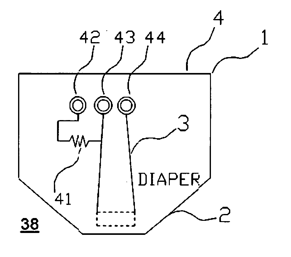
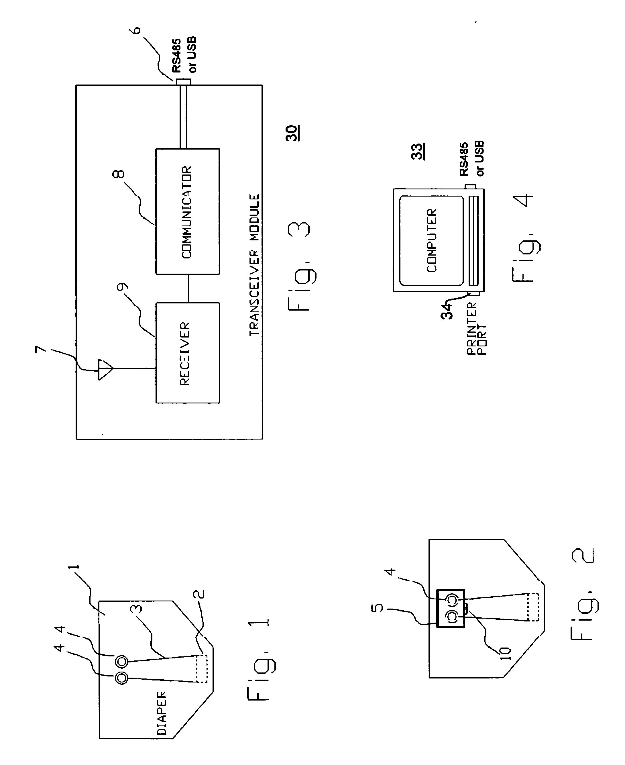
[0061]FIG. 1 is a simplified schematic representation of a diaper 1 equipped with a humidity sensor 2. The diaper has two metal snaps 4 that, in this embodiment, are similar to the ones conventionally used on clothing. The snaps are connected to the humidity sensor by means of two fine enameled copper wires 3 embedded in the fabric of the diaper so they do are not visible from the outside and do not make physical contact with the body of the person wearing the diaper. The diaper, in this specific illustrative embodiment of the invention, contains the female portion of the snaps.

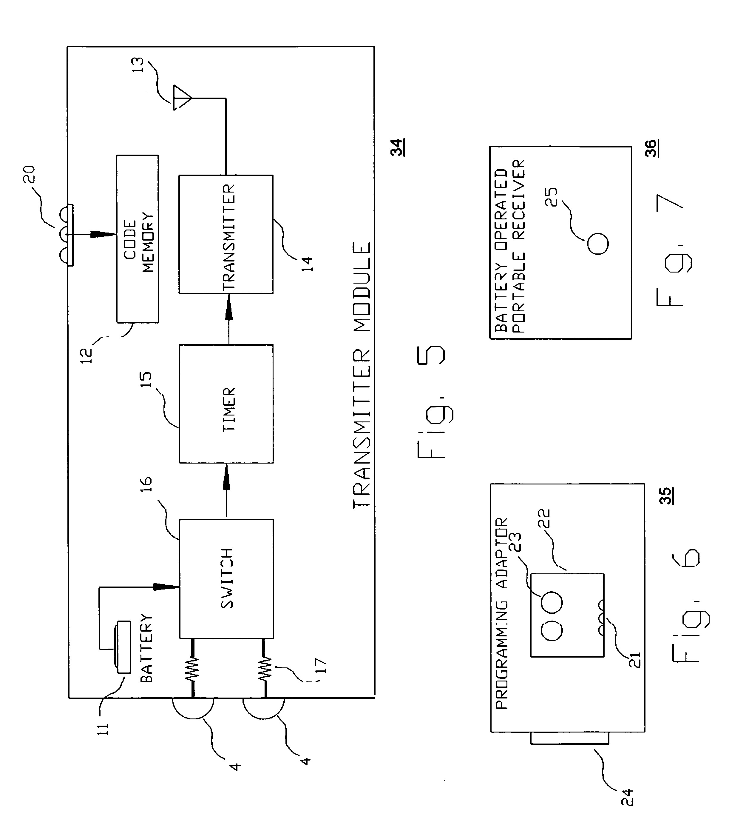
[0062]FIG. 2 is a simplified schematic representation of diaper 1 of FIG. 1 with a transmitter module 5 attached to it. Module 5, is only about an inch square. Module 5 is, in this embodiment, sealed to be water resistant. It is made of a plastic material capable of being sterilized. In this specific illustrative embodiment of the invention the module contains the male portion of the snaps. It also contains ...


PUM


Abstract

A monitoring system identifies a wet diaper by embedding an inexpensive disposable passive humidity sensor, which may be formed of conductive ink, and attaching to the outside of the diaper a detachable transmitting module that is triggered into transmission by the humidity sensor. The transmitting module is sealed and transferable from the wet diaper to a dry one. Uniquely coded data is wirelessly transmitted to a remote receiver. The receiver may be a battery powered portable unit carried by the baby's guardian. In a day care center a multiple function receiver can identify any of several diapers. In hospitals, several strategically located receivers are each capable of recognizing and reporting any wet diaper within its range to a central computer. Low cost and long range are achieved by using a detachable and transportable active transmitter that is not discarded with the wet diaper and therefore can be re-used. False transmissions are prevented by a confirmatory resistance.

Description

RELATIONSHIP TO OTHER APPLICATION [0001] This application is a continuation-in-part patent application of U.S. Ser. No. 10 / 723,604, filed Nov. 25, 2003, which claims the benefit of Provisional U.S. Patent Application Ser. No. 60 / 499,191, filed on Sep. 2, 2003, the disclosures of which are incorporated herein by reference.BACKGROUND OF THE INVENTION [0002] 1. Field of the Invention [0003] This invention relates generally to systems for determining a physical environmental condition from a remote location, and more particularly, to a simple and economical system for announcing a wet diaper condition at a remote monitor. [0004] 2. Description of the Related Art [0005] There is a need for a system that announces to a care giver that a diaper needs to be changed. Babies, for example, wet their diapers any time during the day or night, and without regard to whether they are in or out of their homes. There is a need for parents to be notified when this happens. Child care centers that tend...

Claims


Application Information

Patent Timeline
Patent Type & Authority Applications(United States)
IPC IPC(8): A61F13/42G08B21/20G08B23/00
CPCA61F13/42
Inventor PIRES, HAROLD GEORGE
Owner PIRES HAROLD GEORGE
Learn More