
Low melting temperature silver braze alloy

a technology of braze alloy and low melting temperature, which is applied in the direction of manufacturing tools, electrochemical generators, and solventing apparatus, to achieve the effect of being below the melting point of silver

Inactive Publication Date: 2006-03-02
DELPHI TECH INC
View PDF5 Cites 6 Cited by
  • Summary
  • Abstract
  • Description
  • Claims
  • Application Information

AI Technical Summary

Benefits of technology

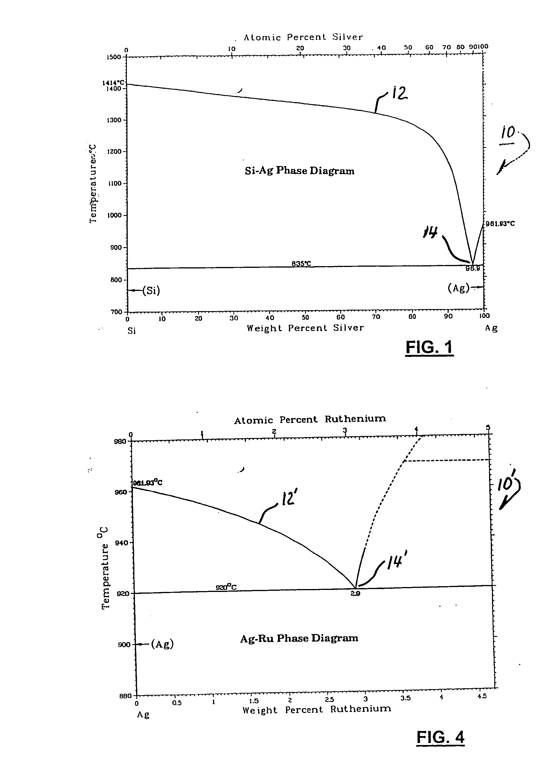
[0008] Briefly described, a brazing alloy in accordance with the invention comprises elemental silver alloyed with another element that serves to reduce the liquidus temperature of the alloy to a temperature below the melting point of silver. In a preferred embodiment, a brazing alloy comprises elemental silver alloyed with elemental silicon in a silver / silicon ratio between about 95 / 5 and 99 / 1, preferably about 97 / 3. Silver melts at 962° C., but small amounts of silicon alloyed with silver depress the alloy liquidus point significantly, the liquidus temperature of a silver and silicon eutectic alloy being about 837° C. Brazing alloys in accordance with the invention are useful in bonding ceramics to ceramics, ceramics to metals, and metals to metals. Such metals are preferably alumina-forming. Copper, vanadium, or other oxygen-reactive surface bonding elements may also be included, and use of such brazing alloys is preferably carried out in an oxidizing atmosphere.

Problems solved by technology

A problem in the use of such alloys is that the liquidus temperature is substantially the melting point of pure silver, 962° C. This temperature is high enough to preclude use of some fuel cell materials which can be damaged by such high temperatures.

Method used


Image

  • Low melting temperature silver braze alloy
  • Low melting temperature silver braze alloy
  • Low melting temperature silver braze alloy

Examples


Embodiment Construction

[0014] Referring to FIG. 1, a phase diagram 10 for silver and silicon alloy mixtures is conventionally displayed, having temperature on the vertical axis as a function of weight percent silicon on the horizontal axis. The solidus / liquidus curve 12 for alloys of silver and silicon extends from pure silver (MP of about 962° C.) to pure silicon (MP 1414° C.). Addition of relatively small amounts of silicon to pure silver serves to depress the alloy liquidus temperature significantly; a eutectic point 14 of about 835° C. exists at a silver / silicon ratio of about 97 / 3. Useful liquidus temperature depressions below the 962° C. melting temperature of silver exist up to about 5% silicon.

[0015] Referring to FIG. 4, a phase diagram 10′ for silver and ruthenium alloy mixtures of a second embodiment, including solidus / liquidus curve 12′ and eutectic point 14′, is shown. In a silver / ruthenium ratio between about 96 / 4 and 99 / 1, preferably about 97 / 3, a liquidus temperature of about 920° C. is ac...


PUM

PropertyMeasurementUnit
liquidus temperatureaaaaaaaaaa

Abstract

A brazing alloy comprising elemental silver alloyed with elemental silicon in a silver / silicon ratio between about 95 / 5 and 99 / 1, preferably about 97 / 3. Small amounts of silicon alloyed with silver depress the alloy liquidus curve significantly, the liquidus temperature of a silver and silicon eutectic alloy being about 837° C. Brazing alloys in accordance with the invention are useful in bonding ceramics to ceramics, ceramics to metals, and metals to metals. Copper, vanadium, or other oxygen-reactive surface bonding elements may also be included. Silver / silicon alloys are useful in applications such as assembly of components of solid oxide fuel cells. A variety of silver / silicon alloy brazes can be used within the same fuel cell so that subsequent brazing can be performed without reliquifying a previous braze. A brazing alloy comprising elemental silver and ruthenium in a silver / ruthenium ratio between 97 / 3 and 99 / 1 is also included.

Description

[0001] This invention was made with United States Government support under Government Contract / Purchase Order No. DE-FC26-02NT41246. The Government has certain rights in this inventionTECHNICAL FIELD [0002] The present invention relates to alloys for joining materials by brazing; more particularly, to silver-containing braze alloys for joining ceramics to metals; and most particularly, to silver braze alloys containing silicon to lower the liquidus temperature. BACKGROUND OF THE INVENTION [0003] Fuel cells which generate electric current by controllably combining elemental hydrogen and oxygen are well known. In one form of such a fuel cell, an anodic layer and a cathodic layer are separated by a permeable electrolyte formed of a ceramic solid oxide, such as yttrium-stabilized zirconium (YSZ). Such a fuel cell is known in the art as a “solid oxide fuel cell” (SOFC). A single cell is capable of generating a relatively small voltage and wattage, typically between about 0.5 volt and abo...

Claims


Application Information

Patent Timeline
Patent Type & Authority Applications(United States)
IPC IPC(8): C22C5/06
CPCB23K35/3006B23K35/322C04B37/006C04B37/026Y02E60/525H01M8/0282H01M2008/1293Y02E60/50C04B2237/125B23K35/0222B23K35/0244B23K35/30B23K35/32
Inventor HALTINER, KARL J. JR.ALEXANDER, GREGORY W.REISDORF, GARY F.
Owner DELPHI TECH INC
Learn More