
Nuclear voltaic cell

a technology of nuclear voltaic cells and voltaic cells, which is applied in the direction of nuclear elements, electric generator control, machines/engines, etc., can solve the problems of no direct conversion method that is efficient and practical, and achieves the effects of small or no maintenance, large electrical energy generation, and small siz

Active Publication Date: 2006-02-16
GLOBAL TECH
View PDF22 Cites 8 Cited by
  • Summary
  • Abstract
  • Description
  • Claims
  • Application Information

AI Technical Summary

Benefits of technology

[0020] As described above, ever since nuclear power was recognized as a viable energy source in the 1950s, considerable research has been performed to find better methods for converting nuclear power into electrical power. However, no direct conversion method has been created that is efficient and practical. In view of the foregoing, an objective of the present invention is to improve upon the prior art by providing a method and apparatus for the efficient, direct conversion of nuclear energy, either radioactive decay energy or fission energy, into electrical energy. More specifically, it is an object of the present invention to provide a self-contained method and apparatus for converting nuclear power to electrical power that can generate large amounts of electrical power for long periods of time without the need for frequent refueling and require little or no maintenance. Another object of the present invention is to provide a method and apparatus that meets the long felt need for a method of converting nuclear energy to electrical energy that is small in size, reliable and can generate large amounts of electrical energy for use in submarines, surface ships, and as a battery to power a whole range of products—including, for example, military equipment, satellites and space vehicles.
[0021] Each embodiment of the current invention relates to the use of a liquid semiconductor in conjunction with a radiation source: either fissile material such as uranium-235 or plutonium, or a radioactive isotope. Use of a liquid semiconductor minimizes the effects of radiation damage, because liquid semiconductors rapidly self-heal, and can be purified or “scrubbed” of fission fragments left from fission events. The current invention comprises different embodiments, several of which are described below.
[0034] In accordance with one embodiment of the invention, there is provided a compact cell for supplying large amounts of electrical energy for a long duration. The cell includes nuclear material for providing nuclear energy, either radiation or fission energy.
[0039] Unlike previous methods for converting nuclear energy to electrical energy using solid semiconductors, the present invention can use fission or high-energy radiation to generate large amounts of electrical power without rapid deterioration of the collection efficiency. This is because, unlike the lattice of a solid semiconductor, the short-range order of a liquid semiconductor is not permanently degraded by the interaction with fission fragments or high-energy radiation. Therefore, in a preferred embodiment of the present invention, the liquid semiconductor is made to flow through the active region of the nuclear voltaic cell (something that is not possible with solid semiconductors), and is purified or scrubbed of unwanted fission fragments and neutron activation products so that its purity and semiconductive properties are not degraded over time, making the conversion device capable of continuous optimum energy conversion. In addition, burned-up fissile material may be replaced while the reactor is operating, avoiding down time for refueling. Because of these advantages, the present invention provides for efficient conversion and the generation of large amounts of electrical power, features that are not possible with solid semiconductor devices.
[0044] In a preferred embodiment of the of the present invention, the liquid semiconductor is made to flow through the active region of the nuclear voltaic cell (something that is not possible with solid semiconductors), and is purified or scrubbed of unwanted decay products so that its semiconductive properties are not impaired over time, making the conversion device capable of continuous optimum energy conversion. Because of these advantages, the present invention provides for efficient conversion and the generation of large amounts of electrical power for long periods of time, things that were not possible with solid semiconductors.

Problems solved by technology

However, no direct conversion method has been created that is efficient and practical.

Method used


Image

  • Nuclear voltaic cell
  • Nuclear voltaic cell
  • Nuclear voltaic cell

Examples


Embodiment Construction

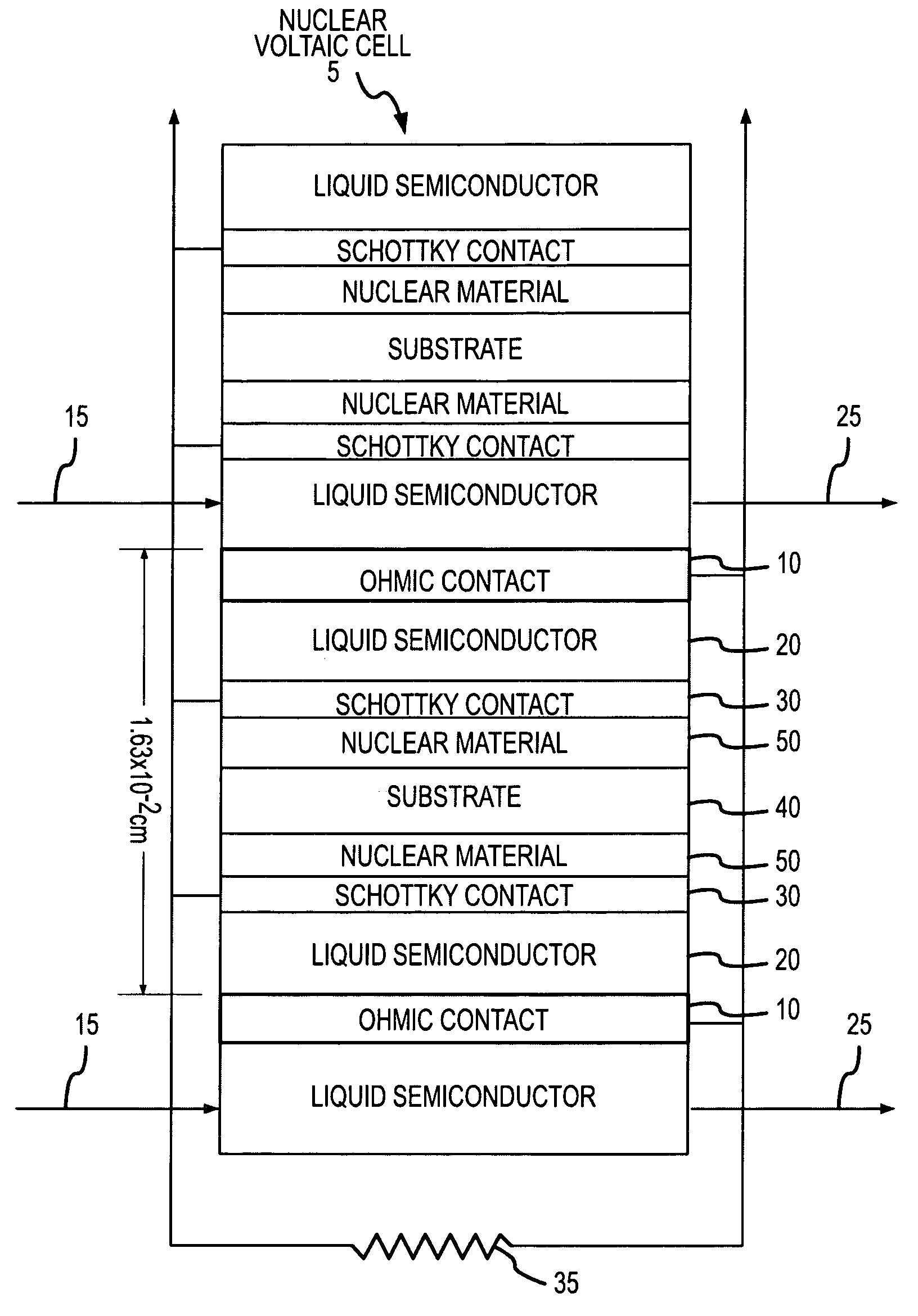
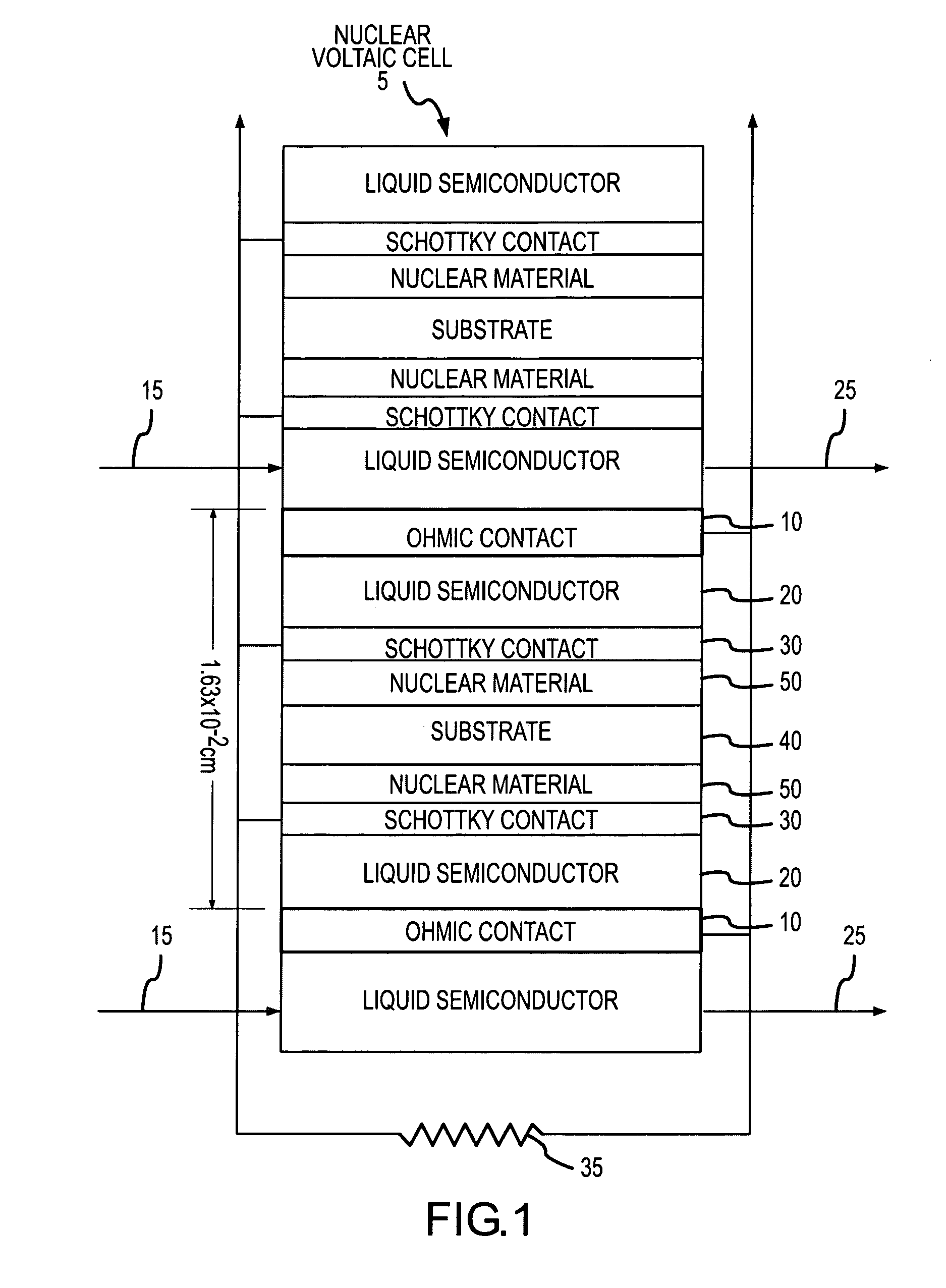
[0057]FIG. 1 shows a cross section through one embodiment of the Nuclear Voltaic Cell 5. In this embodiment, the Liquid Semiconductor 20 is sandwiched between two metal contacts; the Ohmic Contact 10 and the Schottky Contact 30. The device will also function if a low resistance contact is used in lieu of the Ohmic Contact 10. This may be necessary in the case that an ideal Ohmic Contact 10 is not readily available as a result of fundamental or practical reasons.

[0058] As shown in FIG. 1, the Liquid Semiconductor 20 is sandwiched between the two metal contacts, the Ohmic Contact 10 and the Schottky Contact 30. Furthermore, as shown in FIG. 1, the two metal contacts, the Ohmic Contact 10 and the Schottky Contact 30, form a channel through which the Liquid Semiconductor 20 may flow. In a preferred embodiment of the present invention, the Liquid Semiconductor 20 flows in the direction of the Arrow 15 into the channel between the Ohmic Contact 10 and the Schottky Contact 30 and then flo...


PUM

PropertyMeasurementUnit
average energyaaaaaaaaaa
nuclear energyaaaaaaaaaa

Abstract

The invention describes a product and a method for generating electrical power directly from nuclear power. More particularly, the invention describes the use of a liquid semiconductor as a means for efficiently converting nuclear energy, either nuclear fission and / or radiation energy, directly into electrical energy. Direct conversion of nuclear energy to electrical energy is achieved by placing nuclear material in close proximity to a liquid semiconductor. Nuclear energy emitted from the nuclear material, in the form of fission fragments or radiation, enters the liquid semiconductor and creates electron-hole pairs. By using an appropriate electrical circuit an electrical load is applied and electrical energy generated as a result of the creation of the electron-hole pairs.

Description

CROSS REFERENCE TO RELATED APPLICATION [0001] This application is a divisional application of application Ser. No. 10 / 720,035 filed on Nov. 21, 2003 and titled “Nuclear Voltaic Cell,” which is incorporated herein by reference in its entirety.FIELD OF THE INVENTION [0002] The invention relates primarily to a method of and a device for generating electrical power directly from nuclear power, and more particularly to using liquid semiconductors as a means for efficiently converting nuclear energy, either nuclear fission and / or radiation energy, directly into electrical energy. BACKGROUND OF THE INVENTION [0003] Ever since the potential for generating electrical power from nuclear reactions was recognized, scientists have strived to devise the best methods of harnessing nuclear power and putting it to practical use. The main objectives of such research have been to create the most efficient methods of power conversion, power converters that can generate electrical power from nuclear pow...

Claims


Application Information

Patent Timeline
Patent Type & Authority Applications(United States)
IPC IPC(8): G21D7/00G21H1/04H01M
CPCG21H1/04G21H5/00
Inventor TSANG, FRANCIS YU-HEIJUERGENS, TRISTAN DIETERHARKER, YALE DEONKWOK, KWAN SZENEWMAN, NATHANPLOGER, SCOTT ARDEN
Owner GLOBAL TECH
Learn More