Nonvolatile semiconductor memory

a semiconductor memory and non-volatile technology, applied in the field of non-volatile semiconductor memory, can solve the problems of loss of product competitiveness, the current process technology for implementing miniaturized nand flash eeprom cannot keep up, and the process technology is always being pursued to the limit of process technology

Active Publication Date: 2006-01-26
KATANA SILICON TECH LLC
View PDF9 Cites 46 Cited by
  • Summary
  • Abstract
  • Description
  • Claims
  • Application Information

AI Technical Summary

Problems solved by technology

However, since manufacturing conditions become more strict as miniaturization progresses, the current process technology for implementing miniaturized NAND flash EEPROM cannot keep up.
On the contrary, miniaturization is always being pursued to the limit of process technology because high transistor performance of each memory cell transistor is not in great demand, and a systematic layout is possible.
Accordingly, the more minimum pitch locations exist, the more the cost increases, resulting in a loss of product competitiveness.
The process dealing particularly with (3), above, i.e., the pitch between bit line contacts (CB) on active areas is extremely difficult since the aspect ratio of contact holes during processing goes to a maximum.
Since the contact holes are formed to have forward-tapered shapes, the inter-contact distance at the top of the contact hole becomes extremely short when trying to achieve a half pitch at the bottom of the contact holes.
These adjacent contacts may trigger short circuits between bit lines for various reasons.
Such operation may cause possible short circuits between bit lines.
The second reason is that when a dielectric breakdown due to repeated voltage application generates an electrical leakage current as any remaining interlayer film is too thin.
Therefore, the above problems are common to all such devices.
These adjacent contacts may trigger short circuits between bit lines for various reasons.
Technology for formation of contact holes for the bit line contacts 64 aligned in horizontal rows as shown in FIG. 40 demonstrates some improvement as lithography and etching technologies progress, however, the technology is approaching its limit.
However, increasing this area is a problem.
Accordingly with a nonvolatile semiconductor memory typified by a NAND EEPROM, there are problems where the distance between bit line contacts CB becomes narrower, and adjacent bit line contacts can easily short circuit.

Method used


Image

  • Nonvolatile semiconductor memory
  • Nonvolatile semiconductor memory
  • Nonvolatile semiconductor memory

Examples


first embodiment

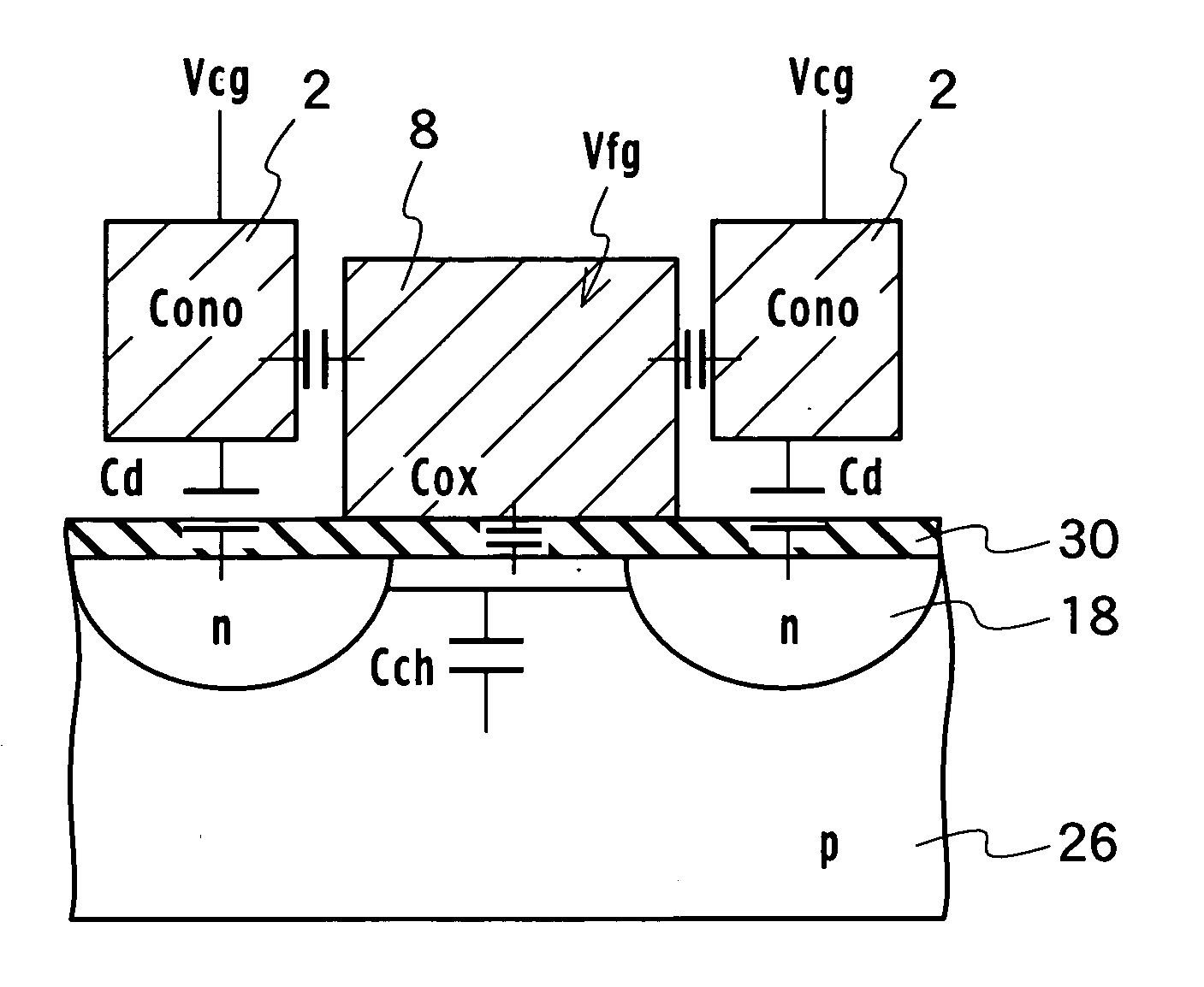
[0082] The basic structure of a memory cell transistor of a nonvolatile semiconductor memory according to a first embodiment of the present invention is, as shown in FIG. 1, a sidewall control gate structure including diffusion layers 18 formed in a semiconductor substrate 26 to be a source region or a drain region, a tunneling insulator film 30 formed on the semiconductor substrate 26, a floating gate 8 formed on a channel region sandwiched between the diffusion layers 18 via the tunneling insulator film 30, a first and second control gates 2 formed adjacent to the two sidewalls of the floating gate 8 via an inter-gate insulator film 40 and facing the diffusion layers 18 that will be a source or a drain.

[0083] The nonvolatile semiconductor memory according to the embodiments of the present invention with the sidewall control gate structure as a basic structure has circuitry and a device cross-sectional structure as shown in FIGS. 3A and 3B. Memory cell transistors MC have a sidewa...

second embodiment

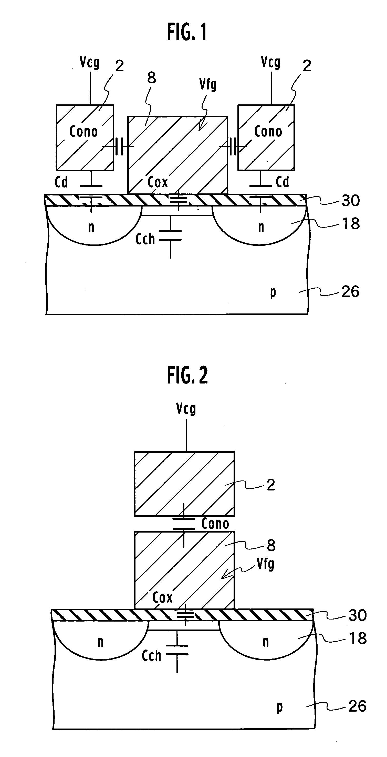
[0104] The basic structure of a memory cell transistor of a nonvolatile semiconductor memory according to the second embodiment of the present invention is, as shown in FIG. 2, a stacked structure including: diffusion layers 18 formed in a semiconductor substrate 26 to be a source region or a drain region; a tunneling insulator film 30 formed on the semiconductor substrate 26; a floating gate 8 formed upon a channel region sandwiched between the diffusion layers 18 via the tunneling insulator film 30; and a control gate 2 formed on the floating gate 8 via an interlayer insulator film.

[0105] According to the sidewall control gate structure, the parasitic capacitance around the floating gate 8 can be reduced, and increasing the value of the capacitance between the control gate 2 and the floating gate 8 allows a decrease in the write-in voltage Vpgm and provides a nonvolatile semiconductor memory capable of dense integration and high-speed performance. On the other hand, two control g...

first modified example

(First Modified Example of Write-in Mode)

[0114] In order to cut off the select gate transistors SG1 and SG2, a back bias voltage is transferred to the inter-unit diffusion layer 80 via neighboring memory cell block regions 62. At this time, pass voltages (DC) are applied to the word lines WL for the neighboring memory cell block regions 62. However, read disturb may be worsened.


PUM


Abstract

A nonvolatile semiconductor memory includes memory cell units, each having memory cell transistors aligned in a column direction and capable of writing and erasing electronic data; and contacts on active areas, arranged on both sides of memory cell unit arrays in which the memory cell units are serially connected in the column direction, and the contacts on active areas are shared by the memory cell unit arrays; wherein, the respective memory cell unit arrays are located having a periodical shift length equal to and or more than the integral multiple length of the periodical length of the memory cell units aligned in the column direction so as to be staggered from each other as compared with neighboring memory cell unit arrays aligned in the row direction.

Description

CROSS-REFERRENCE TO RELATED APPLICATIONS AND INCORPORATION BY REFERENCE [0001] This application is based upon and claims the benefit of priority from prior Japanese Patent Applications P2004-175876 filed on Jun. 14, 2004; the entire contents of which are incorporated by reference herein. BACKGROUND OF THE INVENTION [0002] 1. Field of the Invention [0003] The present invention relates to nonvolatile semiconductor memory characterized in the arrangement of contacts on active areas of the semiconductor memory. [0004] 2. Description of the Related Art [0005] In order to implement a large capacity, low cost NAND flash EEPROM, miniaturization based on a scaling law is essential. However, since manufacturing conditions become more strict as miniaturization progresses, the current process technology for implementing miniaturized NAND flash EEPROM cannot keep up. [0006] The structure of NAND flash EEPROM can be largely divided into cell arrays and peripheral circuits. Less strict design rule...

Claims


Application Information

Patent Timeline
Patent Type & Authority Applications(United States)
IPC IPC(8): G11C8/00G11C16/06G11C16/04H01L21/8247H01L27/02H01L27/115H01L29/788H01L29/792
CPCH01L27/0207H01L27/115H01L27/11524H01L27/11521H01L27/11519H10B41/10H10B41/35H10B69/00H10B41/30
Inventor MATSUNAGA, YASUHIKOARAI, FUMITAKASAKUMA, MAKOTOIGUCHI, TADASHIWATANOBE, HISASHITSUNODA, HIROAKI
Owner KATANA SILICON TECH LLC
Why Eureka
Try Eureka