Flow rate control valve

a flow rate control and valve body technology, applied in fluid pressure control, lighting and heating apparatus, instruments, etc., can solve problems such as complex construction, and achieve the effect of simple construction

Inactive Publication Date: 2006-01-12
TGK
View PDF15 Cites 11 Cited by
  • Summary
  • Abstract
  • Description
  • Claims
  • Application Information

AI Technical Summary

Benefits of technology

[0008] The present invention has been made in view of these problems, and an object thereof is to provide a flow rate control valve of a constant flow-rate control type, which is simple in construction.

Problems solved by technology

However, to control the flow rate to be constant, the conventional flow rate control valve includes the restriction passage for creating the differential pressure, and the differential pressure control valve for controlling the differential pressure across the restriction passage such that it is constant, and hence suffers from the problem of being complicated in construction.

Method used


Image

  • Flow rate control valve
  • Flow rate control valve
  • Flow rate control valve

Examples


first embodiment

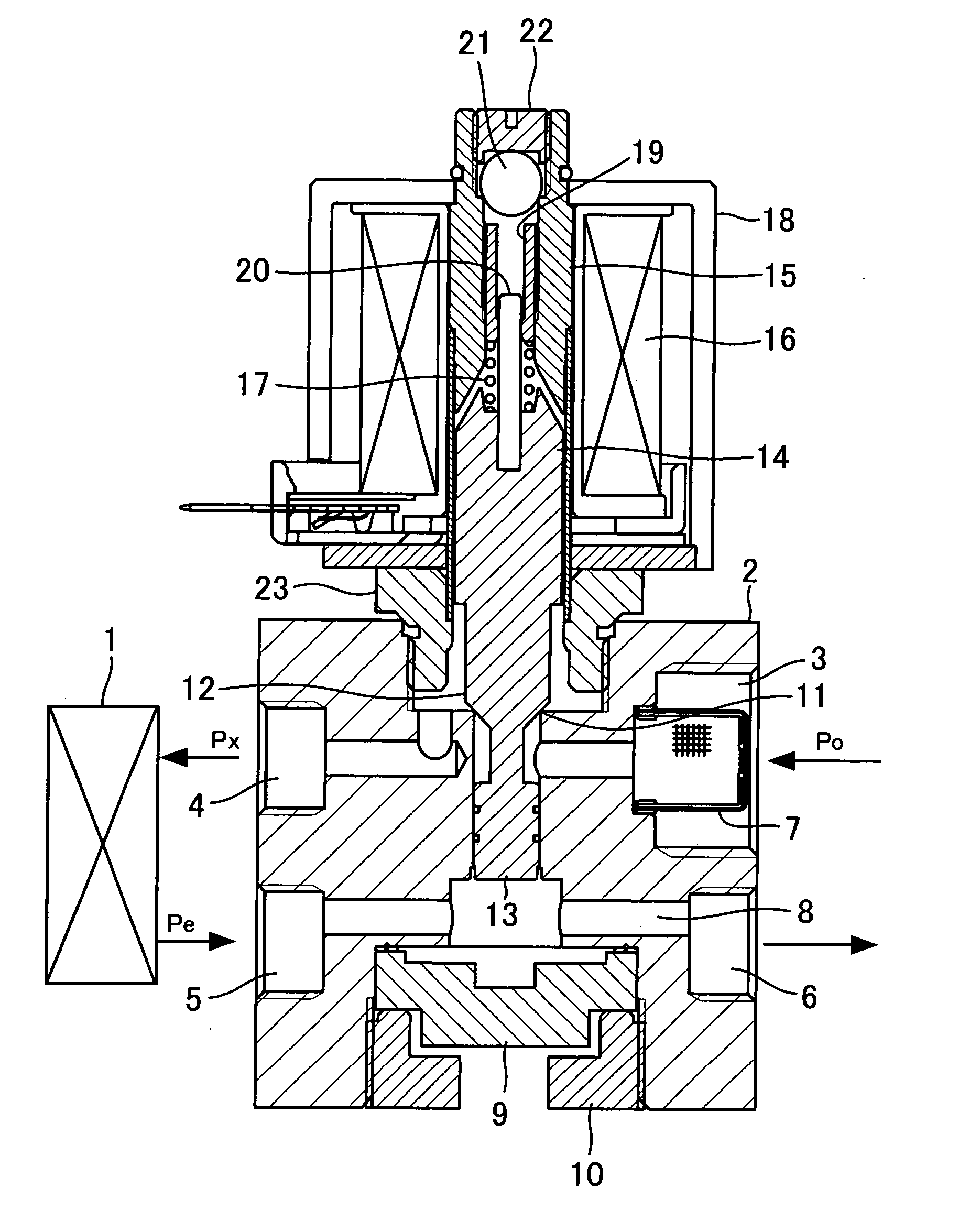
[0017]FIG. 1 is a central longitudinal cross-sectional view of the construction of a flow rate control valve according to the present invention.

[0018] The flow rate control valve is capable of performing constant flow rate control only after it is connected to an evaporator 1, and has a body block 2 provided with a high-pressure refrigerant inlet 3 to which refrigerant at pressure Po is supplied, a low-pressure refrigerant outlet 4 from which refrigerant is delivered to the evaporator 1 while being expanded, a return refrigerant inlet 5 to which refrigerant is returned from the evaporator 1, and a return refrigerant outlet 6 from which the returned refrigerant is delivered to a compressor. The high-pressure refrigerant inlet 3 has a strainer 7 disposed therein in a manner closing a passage formed therein.

[0019] The body block 2 has an upper portion thereof formed with a large-diameter hole, a central portion thereof formed with a cylinder concentric with the large-diameter hole and...

third embodiment

[0034]FIG. 4 is a central longitudinal cross-sectional view of the construction of a flow rate control valve according to the present invention. It should be noted that component elements in FIG. 4 identical or similar to those shown in FIGS. 1 and 2 are designated by identical reference numerals, and detailed description thereof is omitted.

[0035] The flow rate control valve according to the third embodiment is formed by providing the flow rate control valve shown in FIG. 1 with the internal leakage-preventing mechanism of the flow rate control valve shown in FIG. 2 and a backflow preventing mechanism for isolating the evaporator 1 from the refrigeration cycle during stoppage of the automotive air conditioner.

[0036] More specifically, the flow rate control valve according to the present embodiment is configured such that the valve element 12 is intimately seated on a valve seat-forming member 33 press-fitted in a passage between the high-pressure refrigerant inlet 3 and the low-pre...

fourth embodiment

[0039]FIG. 5 is a central longitudinal cross-sectional view of the construction of a flow rate control valve according to the present invention. It should be noted that component elements in FIG. 5 identical or similar to those shown in FIG. 4 are designated by identical reference numerals, and detailed description thereof is omitted.

[0040] In the flow rate control valve according to the fourth embodiment, the check valve 32 disposed in the return passage 8 is moved from the location toward the return refrigerant outlet 6 shown in FIG. 4 to a location toward the return refrigerant inlet 5.

[0041] Therefore, the flow rate control valve is responsive to the differential pressure obtained by adding the differential pressure across the evaporator 1 and the differential pressure across the check valve 32, received by the valve element 12 and the diaphragm 25, to control the differential pressure to be substantially constant, to thereby cause refrigerant to flow into the evaporator 1 at a...


PUM


Abstract

There is provided a flow rate control valve of a constant flow-rate control type, which is simple in construction. The flow rate control valve is configured, by regarding a evaporator as a restriction passage, to include a constant differential pressure control valve for controlling the differential pressure before and after pressure loss caused by passage of refrigerant through the evaporator to be substantially constant. In the constant differential pressure control valve, a valve element receives pressure from the outlet of the flow rate control valve in a valve-closing direction, and a piston receives pressure from the outlet of the evaporator in a valve-opening direction. By controlling the differential pressure between pressure at the inlet of the evaporator and the pressure at the outlet of the evaporator such that it is substantially constant, the constant differential pressure control valve causes the refrigerant to flow into the evaporator at a constant flow rate dependent on electric current that energizes a solenoid. This makes it unnecessary to form a restriction passage in the flow rate control valve, and hence the construction of the flow rate control valve can be simplified, which makes it possible to provide a flow rate control valve manufactured at low cost.

Description

[0001] This application is a continuing application, filed under 35 U.S.C. §111(a), of International Application PCT / JP2004 / 002673, filed Mar. 3, 2004, it being further noted that priority is based upon Japanese Patent Application No. 2003-059353, filed Mar. 6, 2003. BACKGROUND OF THE INVENTION [0002] 1. Field of the Invention [0003] This invention relates to a flow rate control valve, and more particularly to a flow rate control valve used as an expansion device in a refrigeration cycle for an automotive air conditioner, which changes high-temperature, high-pressure refrigerant into low-temperature, low-pressure refrigerant to thereby deliver the refrigerant to an evaporator. [0004] 2. Description of the Related Art [0005] When a refrigeration cycle for an automotive air conditioner uses, as a control valve for controlling a compressor, a differential pressure control type that controls the differential pressure across the compressor or suction pressure of the same such that it is ...

Claims


Application Information

Patent Timeline
Patent Type & Authority Applications(United States)
IPC IPC(8): F25B41/04F04B27/067B60H1/32F04B27/14F25B1/00F25B41/06G05D7/06
CPCF04B27/067F04B27/14F25B41/062F25B2341/063Y02B30/72F25B2600/2505F25B2600/2515G05D7/0635F25B2341/065G05D16/028G05D16/2022Y02B30/70F25B41/34F25B41/335F25B41/345
Inventor HIROTA, HISATOSHI
Owner TGK
Why Eureka
Try Eureka