
Apparatus for real-time monitoring of a workpiece

a technology for workpieces and apparatuses, applied in the direction of optically investigating flaws/contamination, instruments, material analysis, etc., can solve the problems of difficult to optimize the detecting capability of the apparatus, the optimization of the position of the ccd video and the reflection angle of the light emitting module cannot generally be adjusted timely, and the volume of the apparatus is reduced. , the effect of reducing the space required in an application such as a production lin

Inactive Publication Date: 2005-12-15
HON HAI PRECISION IND CO LTD
View PDF7 Cites 12 Cited by
  • Summary
  • Abstract
  • Description
  • Claims
  • Application Information

AI Technical Summary

Benefits of technology

The patent describes an apparatus for real-time monitoring of a workpiece using a laser diode and a digital camera module. The laser diode irradiates the workpiece and the digital camera module captures an optical image signal, which is then transformed into an electrical image signal. The signal processing unit analyzes the electrical image signal to detect any defects or flaws in the workpiece. The main advantage of this invention is that it reduces the space required and improves monitoring efficiency compared to conventional CCD video. The use of a laser diode and aspheric lenses improves the quality of imaging and monitoring.

Problems solved by technology

However, because the CCD video and the light emitting module are generally contained in the one same housing, it is problematic to adjust the CCD video and the light emitting module according to workpieces with different surface properties.
In such circumstances, it is difficult to optimize the detecting capability of the apparatus in order to attain high quality images of workpieces.
In addition, the optimized position of the CCD video and the reflecting angle of the light emitting module cannot generally be adjusted timely.
Therefore the efficacy of the apparatus is limited to some extent.
Furthermore, the overall volume of space occupied by the apparatus is large.
Moreover, when a CCD video picks up a stationary workpiece, it does not necessarily provide better image quality.

Method used


Image

  • Apparatus for real-time monitoring of a workpiece
  • Apparatus for real-time monitoring of a workpiece

Examples


Embodiment Construction

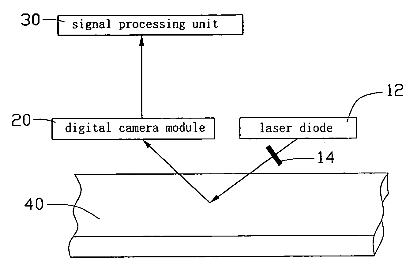
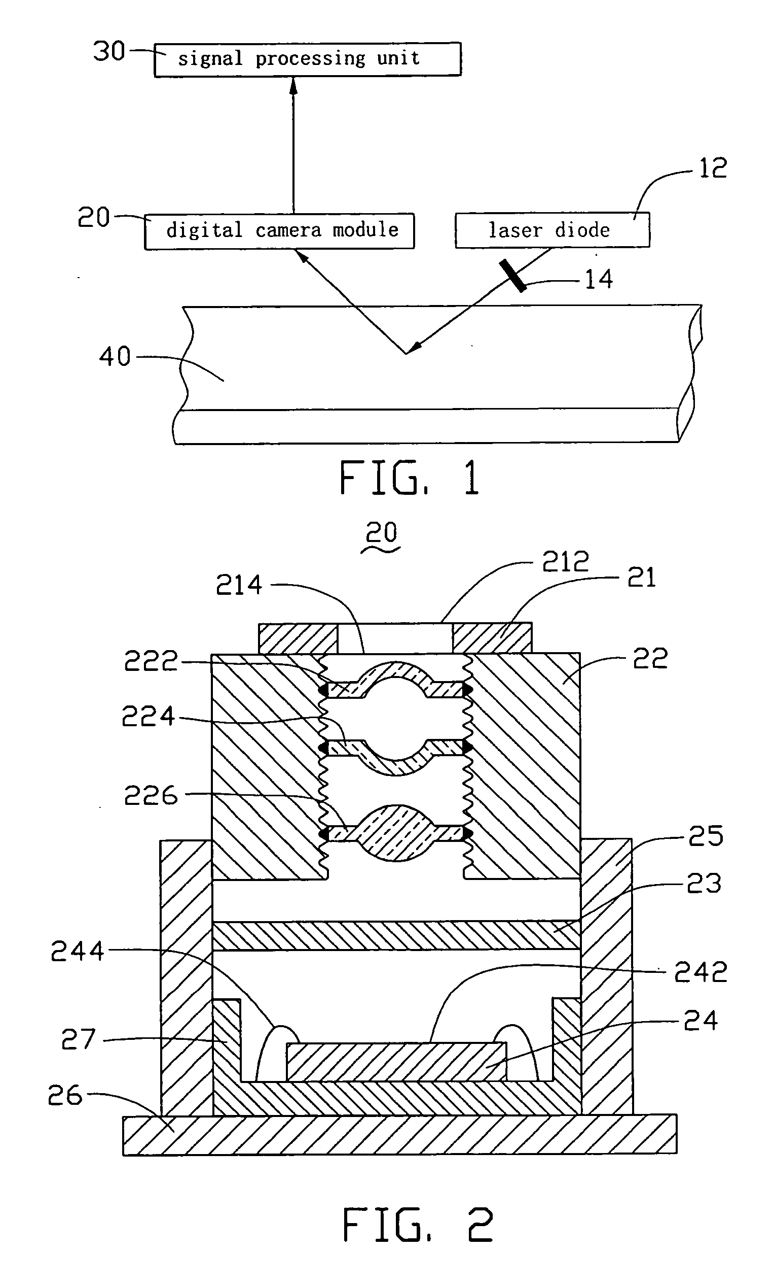
[0012]FIG. 1 schematically shows an apparatus for real-time monitoring of a workpiece, according to a preferred embodiment of the present invention. The apparatus for real-time monitoring is typically used to detect a workpiece 40, to determine whether there are any defects or flaws in the workpiece 40. In this embodiment, the apparatus for real-time monitoring includes a laser diode 12 as a light source, a polarization rotator 14, a digital camera module 20 as an image pickup module, and a signal processing unit 30. The polarization rotator 14 is disposed in the light path of the laser diode 12 above the workpiece 40, and provides polarized light at selected angles. The laser diode 12 emits a light, which is polarized by the polarization rotator 14 and then is incident upon the workpiece 40. The polarized light is reflected by the workpiece 40 to form a reflected light. The reflected light is picked up by the digital camera module 20, which forms an optical image signal of a portio...


PUM

PropertyMeasurementUnit
wavelengthaaaaaaaaaa
optical imageaaaaaaaaaa

Abstract

An apparatus for real-time monitoring of a workpiece (40) includes a laser diode (12) emitting a light irradiating the workpiece, a digital camera module (20) imaging the workpiece and forming an optical image signal, and a signal processing unit (30) electrically connected with the laser diode and the digital camera module respectively The optical image signal is transformed by the digital camera module into an electrical image signal, which is transmitted to the signal processing unit. The signal processing unit processes and analyzes the electrical image signal to determine whether there are any defects or flaws in the workpiece. By employing the digital camera module, the volume of the apparatus is reduced. In addition, the monitoring efficiency is improved because of the application of a laser diode. Furthermore, the digital camera module adopts aspheric lenses for improved quality imaging of the workpiece.

Description

FIELD OF THE INVENTION [0001] The present invention relates to apparatuses for real-time monitoring of workpieces such as those on a production line, and particularly to an apparatus with a digital camera module for real-time monitoring of workpieces. BACKGROUND OF THE INVENTION [0002] During processes such as precision machining, surface treatment, electronic packaging and semi-conductor manufacturing, it is generally necessary to monitor a workpiece in real time in order to timely determine whether there are any defects or flaws in the workpiece. This helps ensure timely troubleshooting of production problems that may arise, and a high yield rate of final products. [0003] Conventionally, an apparatus for detecting machined workpieces includes a light emitting module, and a CCD (Charge Coupled Device) video which photographs the workpiece and forms an optical image signal. The optical image signal picked up by the CCD video is then transformed into a digital image signal. The digit...

Claims


Application Information

Patent Timeline
Patent Type & Authority Applications(United States)
IPC IPC(8): G01N21/21G01N21/88G06K9/00
CPCG01N21/8806G01N21/21
Inventor CHEN, GA-LANE
Owner HON HAI PRECISION IND CO LTD
Learn More