
Organic waste treatment apparatus

a waste treatment and organic technology, applied in the field of food waste treatment and novel waste treatment apparatus, can solve the problems of waste disposal cos

Inactive Publication Date: 2005-11-24
BIOSYS
View PDF8 Cites 19 Cited by
  • Summary
  • Abstract
  • Description
  • Claims
  • Application Information

AI Technical Summary

Benefits of technology

[0014] size reduction means for reducing the size of waste material introduced to the vessel, wherein said means divides the interior vessel space into upper and lower regions,
[0019] The size reduction means is provided so as to reduce the size of introduced waste material to particles / pieces of an average diameter / dimension size of approximately 2 to 10 mm. It has been found that by reducing the size of introduced waste material to particles / pieces greatly increases the rate of composting which may be achieved and assists in the production of a well mixed and uniform, composted product. The size reduction means also assists in the thorough mixing of the introduced waste material. The apparatus is preferably arranged so that all waste material must pass through the size reduction means when passing from the upper region to the lower region of the vessel.
[0021] The loading hatch may be located in the side wall(s) adjacent to the top wall, but more preferably, is located in the top wall. The loading hatch may be conveniently adapted for controlled or automated opening and closing. Preferably, the loading hatch, when closed, forms an air-tight seal to prevent escape of any odourous gas or “process air” from the vessel.
[0022] The discharge hatch may be located in the side wall(s) adjacent to the base wall, but more preferably, is located in the base wall. The discharge hatch may be conveniently adapted for controlled or automated opening and closing. Preferably, the despatch hatch, when closed, forms an air-tight and liquid seal to prevent escape of any odourous gas or process air and liquids (ie leachates) from the vessel.
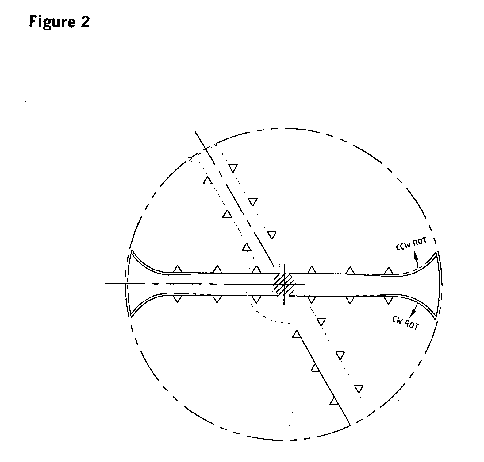
[0025] Such a rotatable shaft may also be provided with fittings, other than the one or more blades or cutting edges. For example, on a portion of the rotatable shaft that resides within the upper region of the vessel, there may be provided one or more spreader or mixer bar(s) to assist in evenly distributing and mixing introduced waste material. Also, on a portion of the rotatable shaft that resides within the lower region of the vessel there may be provided one or more mixing bar(s) to ensure that the waste material in the lower region of the vessel is moved by agitation therefore ensuring even and consistent flow of composting materials. Further, on a portion of the rotatable shaft adjacent to the base wall, there may be provided one or more sweeper bar(s) or plate(s) to sweep composted material adjacent to the base wall towards and out of the discharge hatch. The rotatable shaft preferably operates both in a clockwise and anti-clockwise direction, and all rotating bars and blades or cutting edges are preferably symmetric is plan view to allow for effective action in both directions.
[0027] introducing waste material into an apparatus for aerobically composting waste material, said apparatus comprising a vertically-orientated vessel comprising a top wall, base wall and side wall(s) defining an interior vessel space, the interior vessel space being divided into upper and lower regions by a size reduction means for reducing the size of waste material introduced to the vessel, and wherein the introduction of waste material is to the upper region of the vessel, and

Problems solved by technology

Food waste and other putrescible organic waste is a major contributor to the cost of waste disposal.
In addition, the disposal of wastes such as food waste and other putrescible organic waste is particularly undesirable due to their high water and nutrient content, leading to the release of organic acids and other compounds during anaerobic decomposition which are major contributors to the negative environmental impacts associated with landfills (Recycled Organics Unit, 2001a, Greenhouse gas emissions from composting facilities, Report for Central Coast Waste Board, NSW, September 2001).
Such shortages of landfill sites, and the resistance of communities to the establishment of new landfill sites on health, environmental and monetary concerns, is urgently impelling the need to divert recyclable wastes from landfill.

Method used


Image

  • Organic waste treatment apparatus
  • Organic waste treatment apparatus
  • Organic waste treatment apparatus

Examples


example 1

Materials and Methods

Description of the Apparatus and Process.

[0052] A trial was conducted to objectively characterise the performance of an organic waste treatment apparatus according to FIG. 1, in terms of processing performance (ie retention time and processing capacity), product quality and stability, and associated environmental impacts (eg odour, pests and leachate).

[0053] The apparatus was designed for on-site conversion of food waste into a saleable composted waste material product, which would be capable of being operated by a single user.

[0054] The apparatus comprised a composting chamber with an internal volume of 2.4 m3. The apparatus was provided with an analogue temperature feedback mechanism (comprising a digital thermostat controller) controlled the injection of compressed air from two reciprocating air compressors via a ring main installed on the bottom outer perimeter of the composting chamber and into a bearing housing at the base of a central rotatable shaf...


PUM

PropertyMeasurementUnit
volumeaaaaaaaaaa
volumeaaaaaaaaaa
volumeaaaaaaaaaa

Abstract

A composting system including a vertically-orientated vessel with a range of mechanisms attached to a vertically oriented central mounted rotating shaft, including rotatable size reduction blade(s), agitation mechanism(s), and discharge blade / mechanism(s). The composting system includes internal size reduction mechanism for reducing the size of waste and / or organic material introduced to the vessel. The composting system includes a loading hatch through which material may be introduced into the vessel, a discharge hatch through which material may be removed from the lower region of the vessel, and a source of air to maintain aerobic conditions within said vessel. When the apparatus is in use, material introduced to the vessel moves from the upper region of the vessel gravitationally and via agitation through a zone of size reduction to the lower region of the vessel. Process conditions within the vessel are controlled via intervention by an operator and via electronic control mechanism, which can monitor operating conditions such as temperature and loading rate (for example), to manage air injection, mechanical agitation and size reduction such that composting proceeds efficiently and at an optimal rate.

Description

FIELD OF THE INVENTION [0001] The present invention relates to the field of waste treatment, particularly food waste treatment. The present invention provides a novel waste treatment apparatus which may be used, for example, as an on-site waste treatment vessel at businesses where significant amounts of food waste are produced (eg accommodation enterprises, fruit and vegetable shops and markets, retirement villages and multi-unit dwellings, supermarkets, restaurants / cafes / cafeterias, government workplaces, and hospitals). BACKGROUND TO THE INVENTION [0002] Food waste and other putrescible organic waste is a major contributor to the cost of waste disposal. This is due largely to the present need to transport such wastes to specific landfill sites which are often at significant distances from the sites of the waste production. In addition, the disposal of wastes such as food waste and other putrescible organic waste is particularly undesirable due to their high water and nutrient cont...

Claims


Application Information

Patent Timeline
Patent Type & Authority Applications(United States)
IPC IPC(8): C05F17/00C05F17/02
CPCC05F17/0072C05F17/027C05F17/0247Y02P20/145C05F17/70C05F17/979C05F17/95Y02W30/40
Inventor CAMPBELL, ANGUS
Owner BIOSYS
Learn More