
Cyclic redundancy check circuit for use with self-synchronous scramblers

a cyclic redundancy check and self-synchronous scrambler technology, applied in the direction of coding, instruments, code conversion, etc., can solve the problems of receiver failure, possible for a malicious subscriber, and much more difficult for a malicious user to defeat the effect of frame synchronous scrambler

Inactive Publication Date: 2005-11-17
MICROSEMI STORAGE SOLUTIONS
View PDF13 Cites 13 Cited by
  • Summary
  • Abstract
  • Description
  • Claims
  • Application Information

AI Technical Summary

Problems solved by technology

The frame-synchronized scrambler was added to make it much more difficult for a malicious user to defeat the effects of the frame synchronous scrambler.
One drawback of a frame-synchronized scrambler is that it is a known, relatively short (27−1) pseudo-random sequence and it is possible for a malicious subscriber to attempt to mimic this pattern within the data he sends.
The result is that if the subscriber data lines up with the SONET / SDH scrambler correctly, a long string can occur with no transitions, which in turn can cause the receiver to fail.
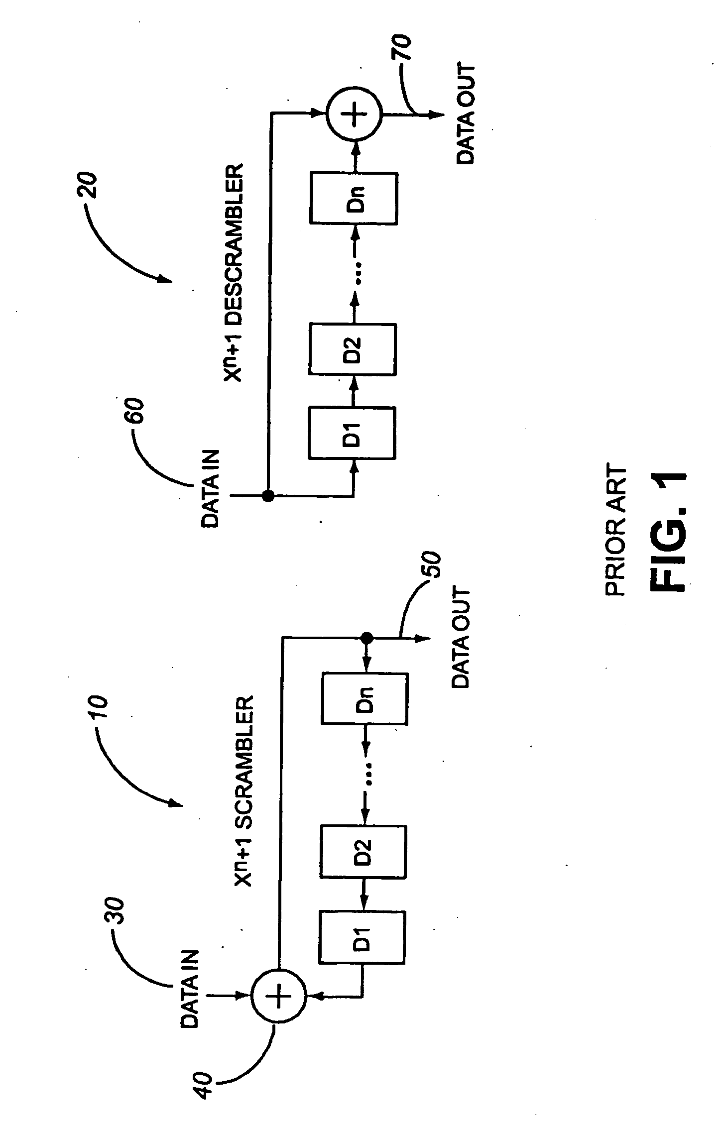
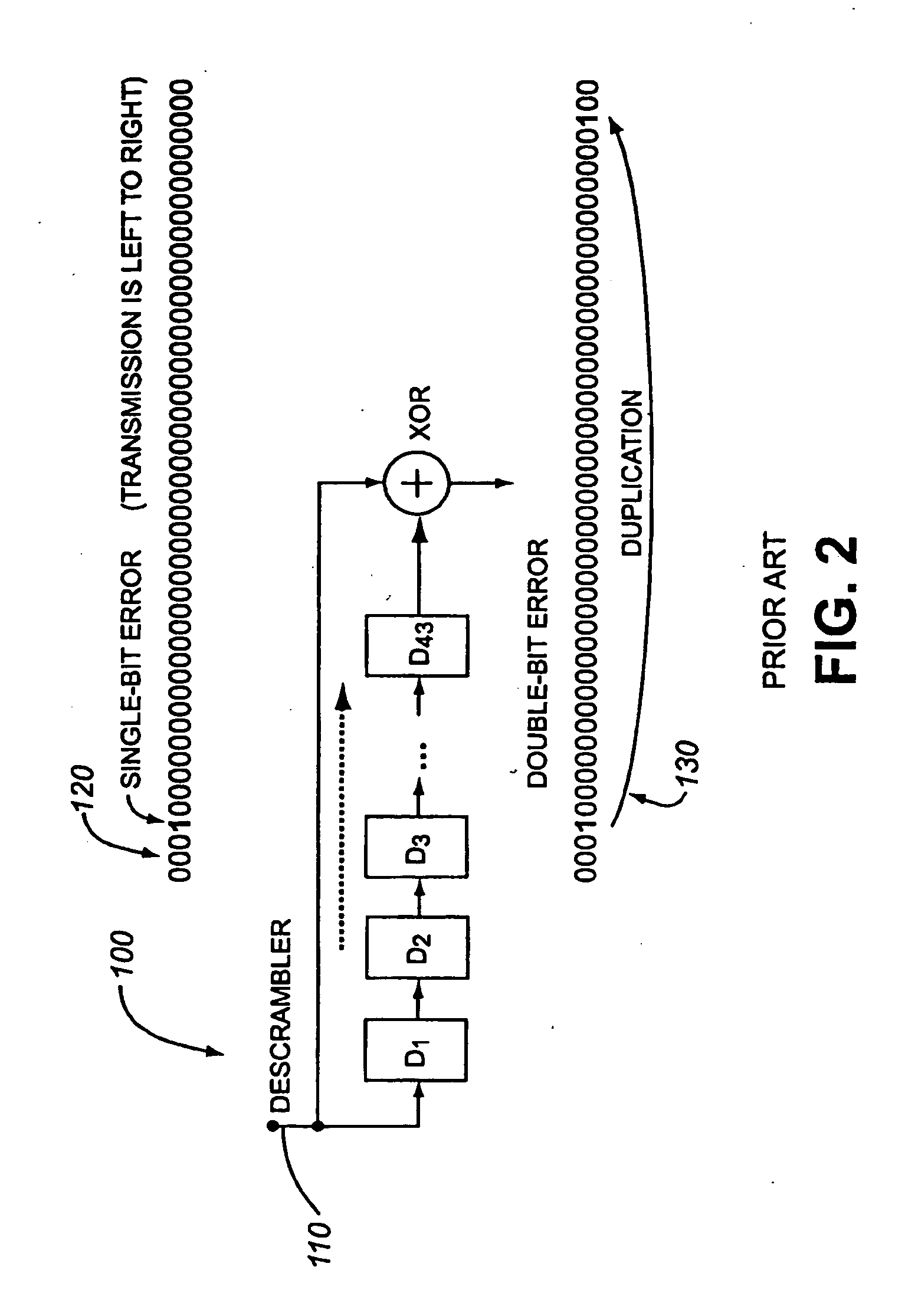
The drawback to a self-synchronous scrambler is that any errors occurring on the transmission channel will be duplicated 43 bits later by the descrambler.

Method used


Image

  • Cyclic redundancy check circuit for use with self-synchronous scramblers
  • Cyclic redundancy check circuit for use with self-synchronous scramblers
  • Cyclic redundancy check circuit for use with self-synchronous scramblers

Examples


first embodiment

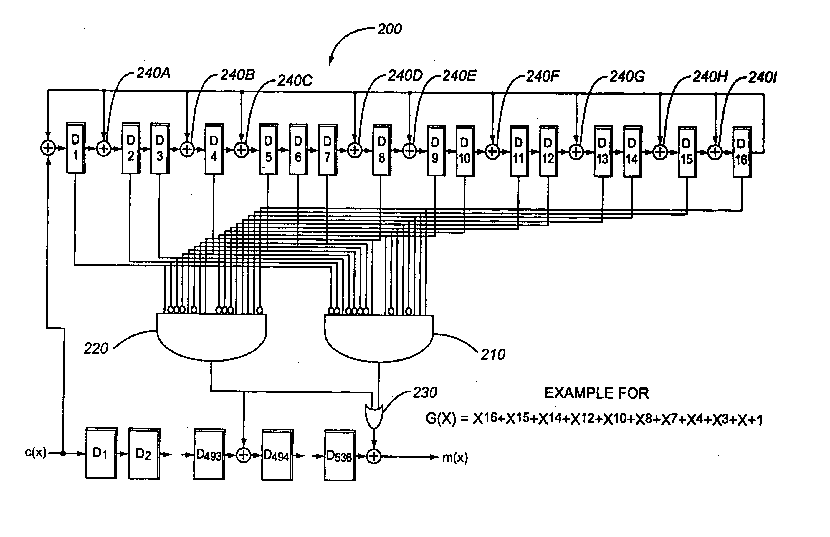
[0041]FIG. 3 illustrates a circuit 200 for detecting and correcting single and double bit errors according to the present invention. The first embodiment is intended for an initial proposed transparent GFP superblock CRC-16. The circuit 200 consists of a plurality of bit circuit elements D1, D2, D3, D4, D5, D6, D7, D8, D9, D10, D11, D12, D13, D14, D15, D16, two logic AND gates 210, 220, an OR gate 230, and a plurality of input bit stream circuit elements D1, D2, . . . , D493, D494, . . . , D536, as shown in FIG. 3. The bit circuit elements may be implemented as bit registers, or other circuit elements such as flip-flops or transistors. The CRC polynomial implemented in the circuit 200 is G(x)=x16+x15+x14+x12+x10+x8+x7+X4+x3+x+1.

[0042] According to the circuit 200 of FIG. 3, the input stream is a GFP superblock, essentially a 536 bit block, which is input into circuit elements D1 through D536. On a bit-by-bit basis, the D1 through D16 bit circuit elements receive input from the input...

second embodiment

[1046]FIG. 4 illustrates a circuit 300 for detecting and correcting single and double bit errors according to the present invention. The second embodiment is intended for a final version transparent GFP superblock CRC-16. The circuit 300 differs from that of FIG. 3, in that bitwise operations are dictated by a different G(x) polynomial. The CRC polynomial implemented in this circuit 300 is G(x)=x16+x15+x14+x12+x10+x4+X3+x2+X+1.

[1047] It should be mentioned that while the circuits of FIGS. 3 and 4 detect double bit errors generated by a descrambler, the circuits of the present invention detect single bit, double bit, and triple bit errors derived from any number of other sources. The 536 bit block need not be derived from a descrambler, such as is used on a GFP CRC-16. The circuit of the present invention may derive a 536-bit superblock, prior to processing by the circuit of the present invention. Furthermore, the art that the present invention may be embodied in other circuitry. For...

third embodiment

[1048]FIG. 5 is a block diagram of a circuit 400 for an 8-bit wide parallel implementation according to the present invention. As compared to the serial bit implementation of FIGS. 3 and 4, the error detection logic 410 outputs an 8-bit wide output to the OR gate 420. In an 8-bit wide parallel implementation, errors are detected for an 8-bit wide block. The single and double errors are corrected in the same manner as in the implementation of FIG. 4 with the advantage that operating on 8-bit data blocks allows the circuit to operate at ⅛ the data path clock speed of a serial implementation such as in FIGS. 3 and 4. The data path clock speed reduction is a significant advantage for high-speed data transmission.

[1049] In FIG. 5, the process implemented by the circuit 400 is similar to that of FIGS. 3 and 4. The parallel CRC-16 generator consists of a bit circuit elements which are coupled to sequentially receive and store a sequential 16 bits derived from an 8-bit wide input stream 450...


PUM


Abstract

The present invention provides a circuit for detecting and correcting errors in a bit stream. The circuit consists of a plurality of circuit elements, a least one operation circuit means, and at least two logic gates. The logic gates receive inputs from the plurality of circuit elements. The plurality of circuit elements are coupled to receive and store a portion of a bit stream. The operation circuit elements perform bitwise operations on the contents of at least two of the circuit elements. The bitwise operations are dictated by a cyclical redundancy check (CRC) polynomial and are used to perform the CRC error detection division operation. At the end of the division process for the data to be checked, each circuit element corresponds to a bit in a bit error pattern syndrome and the logic gates determine if the contents of the circuit elements match specific bit error patterns. The circuit causes the state of at least one bit in the bit stream to change if the contents of the plurality of circuit elements match one of the specific bit patterns. The circuit is advantageous in that it may detect single bit errors, and double bit errors that may be caused by error duplication characteristic of a scrambler.

Description

CROSS REFERENCE TO RELATED APPLICATIONS [0001] This application is a continuation of U.S. patent application Ser. No. 10 / 147,880, filed on May 20, 2002, the contents of which are incorporated herein by reference.FIELD OF INVENTION [0002] This invention relates to the error detection and correction by a 16-bit Cyclic Redundancy Check (CRC-16) generation circuit. BACKGROUND TO THE INVENTION [0003] Cyclic Redundancy Check (CRC) is an important aspect in the error-detecting capabilities of many protocols, such as the Ethernet local area network, protocol. CRC provides a number of bits (usually 16 or 32) generated from, and appended to the end of, a block of data to provide error detection. A message receiver generates a CRC from the block of data and compares it to the CRC appended to the received message. If the appended CRC matches the generated CRC, then there is a high probability that the received message has not been corrupted. [0004] One standard 16-bit generator polynomial is re...

Claims


Application Information

Patent Timeline
Patent Type & Authority Applications(United States)
IPC IPC(8): H03M13/09
CPCH03M13/09
Inventor GORSHE, STEVEN SCOTT
Owner MICROSEMI STORAGE SOLUTIONS
Learn More