
Advanced optics for rapidly patterned laser profiles in analytical spectrometry

a laser profile and analytical spectrometry technology, applied in the field of mass spectrometry, can solve the problems of limiting both techniques, exceedingly challenging, and nsom techniques currently limited to generating symmetrical (typically round) spot shapes, and achieves rapid patterning, eliminate perspective foreshortening, and reduce the effect of nsom techniques

Inactive Publication Date: 2005-11-03
TEXAS A&M UNIVERSITY
View PDF25 Cites 8 Cited by
  • Summary
  • Abstract
  • Description
  • Claims
  • Application Information

AI Technical Summary

Benefits of technology

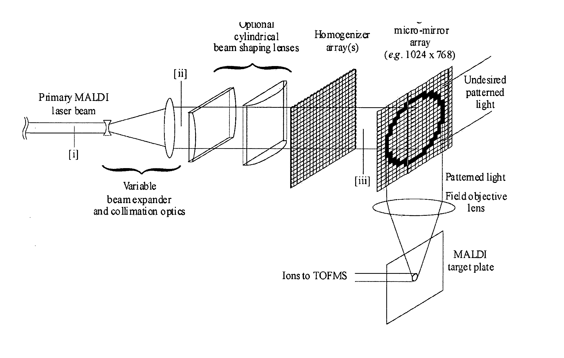
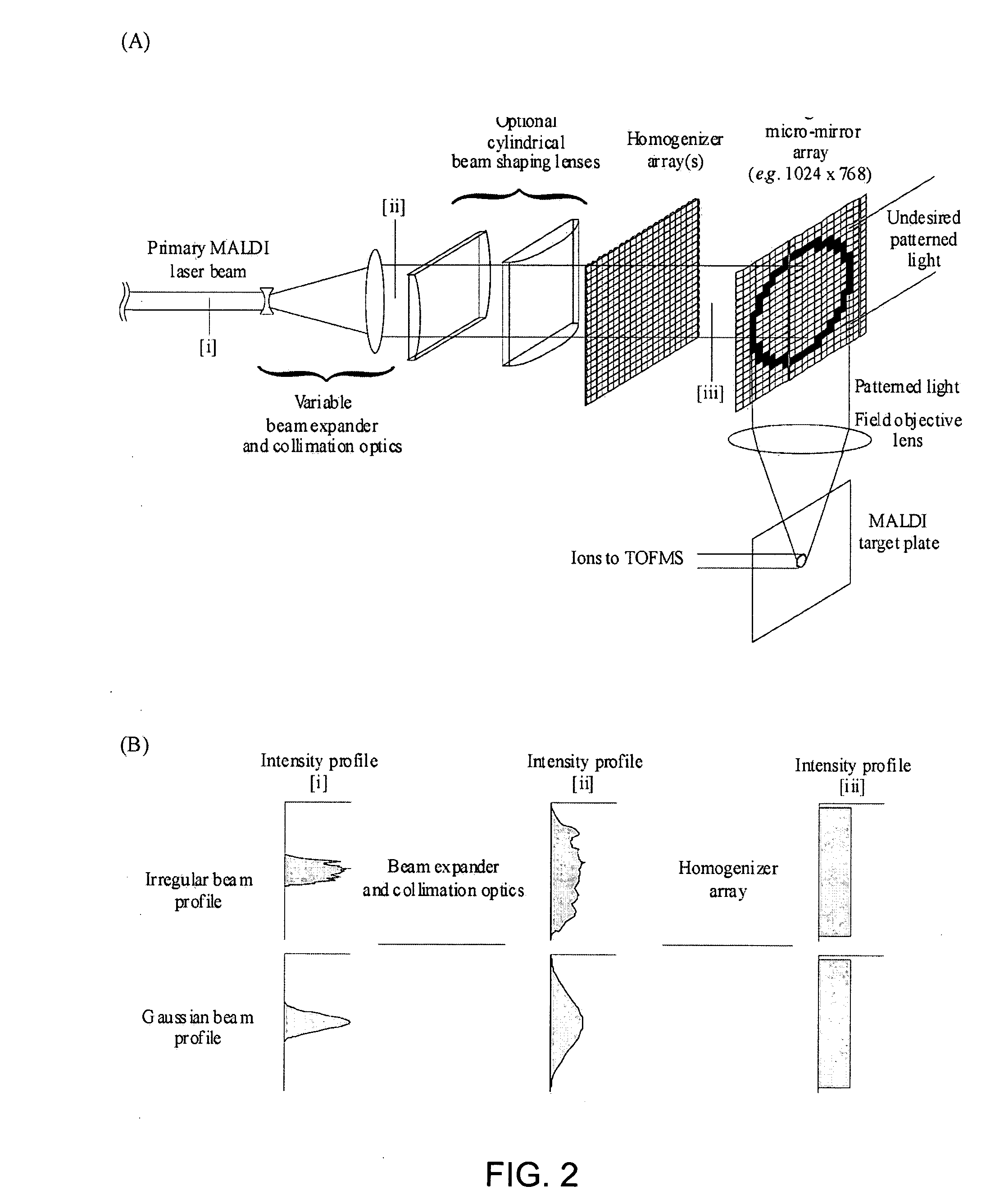
[0009] The present invention is directed to a novel arrangement of optical devices for the rapid patterning of laser profiles used for desorption and / or ionization sources in analytical mass spectrometry. Specifically, the new optical arrangement provides for a user-defined laser pattern at the sample target that can be quickly (μs-timescale) changed to different dimensions (or shapes) for subsequent laser firings. For each firing, the pattern of light can be constructed so that noncongruent regions are irradiated simultaneously, for ionizing multiple regions of interest or for providing a multiple ion sources for multiple mass spectrometers. The large number of wavelets constituting the light pattern can be used to project a conjugate perspective distorted image to eliminate perspective foreshortening at the image plane. Further, the laser profile can be repositioned on the target sample rather than conventional means of mechanically moving the sample target to analyze different spatial regions of the sample. The rapid patterning of laser profiles, according to the present invention, will significantly impact many areas of mass spectrometry ranging from imaging mass spectrometry (e.g., by patterning the laser spot to irradiate a region of interest) to increased throughput when coupled with high repetition rate laser technology.
[0014] The present invention is directed to a system and method which a novel arrangement of optical devices for the rapid patterning of laser profiles used for desorption and / or ionization sources in analytical mass spectrometry. Specifically, the new optical arrangement provides for a user-defined laser pattern at the sample target that can be quickly (μs-timescale) changed to different dimensions (or shapes) for subsequent laser firings. Alternatively, the laser profile can be repositioned on the target sample rather than conventional means of moving the sample target to analyze different spatial regions of the sample. The rapid patterning of laser profiles, according to the present invention, will significantly impact many areas of mass spectrometry ranging from imaging mass spectrometry (e.g., by patterning the laser spot to irradiate a region of interest) to increased throughput when coupled with high repetition rate laser technology.
[0016] The present invention differs from the prior art in that an innovative optical arrangement comprising a DMA is used to spatially pattern light onto a sample target surface for the purposes of desorption and / or ionization of material for mass spectrometric analysis. By defining the dimensions and shape of the laser radiation at the surface, one can precisely control the sample interrogation region in imaging mass spectrometry techniques. For example, complex shapes, such as individual cells in a tissue section (e.g., exhibiting diseased vs. healthy morphology), can be easily selected for selective irradiation and subsequent mass analysis. Further, spatial resolution can be significantly enhanced (ca. 0.5 to 2 μm) over conventional MALDI imaging mass spectrometry (ca. 10 to 20 μm), by using the small spatial mirror elements of the DMA rather than slits to aperture the laser radiation. A second application of this optical arrangement is to rapidly (ca. 10 to 20 μs) raster laser irradiation across the sample, at a high repetition rate, for increased throughput and enhanced sensitivity in mass spectrometric applications. This is in contrast with conventional methods of physically repositioning the sample target with respect to the static optical arrangements typically used.

Problems solved by technology

However, both techniques are primarily limited to the analysis of atomic ions and small molecules (typically<500 amu) and ultimately provide spatial imaging resolution that directly depends on the focusing properties of the optics (i.e., ion or photon optical elements) used to define the ionizing beam.
Experimentally, this is exceedingly challenging in MALDI where the sample topography can easily exceed micrometer(s) deviation in elevation unless stringent and difficult sample preparation procedures are used.
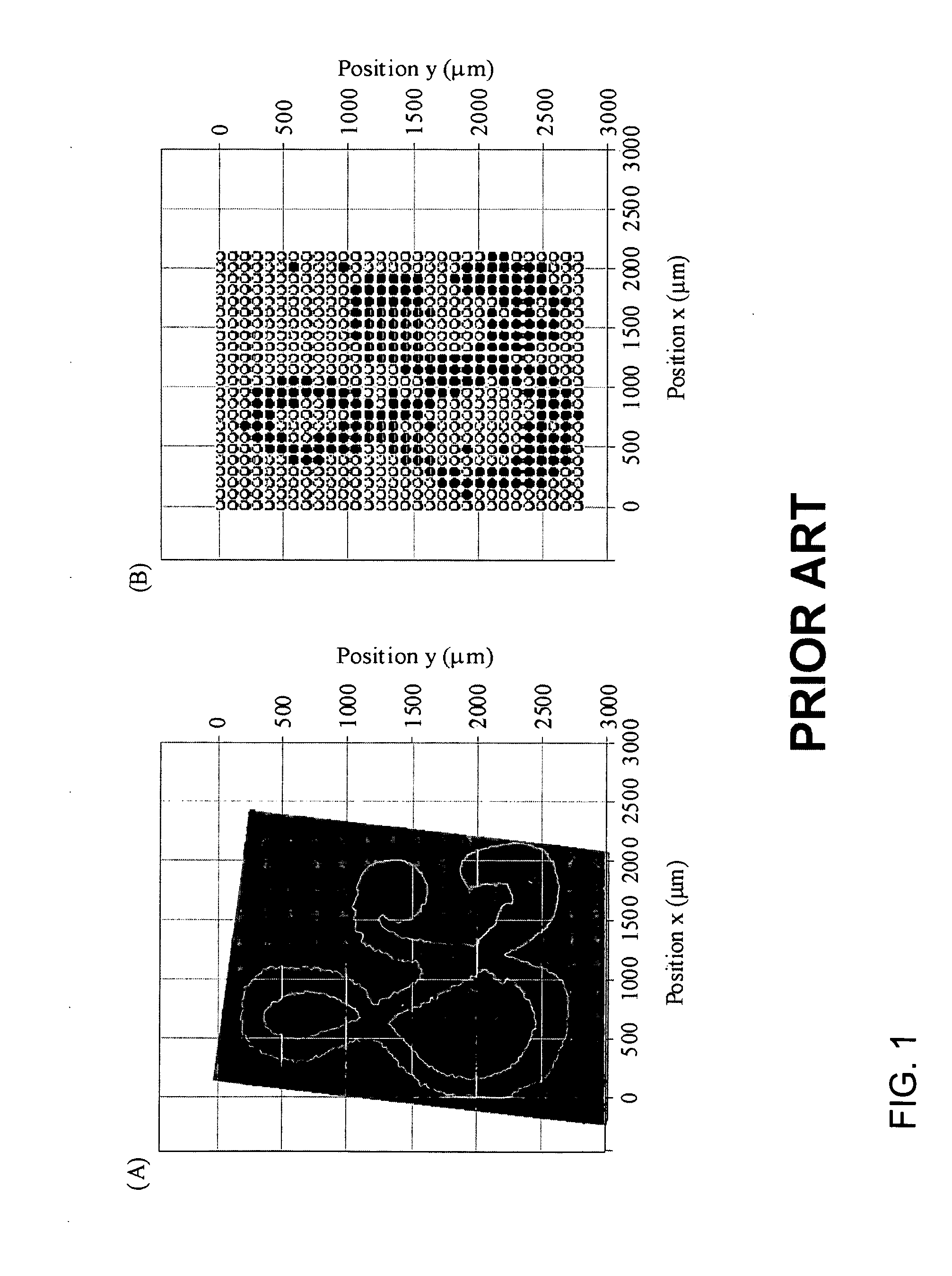
Further, NSOM techniques are currently limited to generating symmetrical (typically round) spot shapes at the image plane (i.e., sample target) and cannot be easily changed to user defined dimensions or shape.

Method used


Image

  • Advanced optics for rapidly patterned laser profiles in analytical spectrometry
  • Advanced optics for rapidly patterned laser profiles in analytical spectrometry
  • Advanced optics for rapidly patterned laser profiles in analytical spectrometry

Examples


Embodiment Construction

[0023] As used herein, “a” or “an” means one or more, unless otherwise indicated. The singular encompasses the plural and the plural encompasses the singular.

[0024] As used herein, the term “fluidly coupled”, with respect to two or more optical components refers to the flow of light or matter between the components, so that the light and / or matter output of one component is substantially the input of one or more other components.

[0025] As used herein, “inspecting” or “inspection”, in the context of performing work on a sample, is defined in its broadest terms, and includes, but is not limited to, inspection of the entire sample or the inspection of one or more selected portions or spatial regions of a sample. Although the term “inspection” may include both the sampling of material and the subsequent analysis of the sampled material, it also includes sampling of the material itself without any further chemical analysis. As an example, the laser desorption of part of a sample consti...


PUM


Abstract

The present invention is directed to a novel arrangement of optical devices for the rapid patterning of laser profiles used for desorption and / or ionization sources in analytical mass spectrometry. Specifically, the new optical arrangement provides for a user-defined laser pattern at the sample target that can be quickly changed (on a microsecond timescale) to different dimensions (or shapes) for subsequent laser firings.

Description

[0001] This application claims priority to U.S. Provisional Application Ser. No. 60 / 544,098, filed on Feb. 12, 2004.STATEMENT REGARDING FEDERALLY SPONSORED RESEARCH OR DEVELOPMENT [0002] This work has been funded in whole or in part by U.S. government funding. The government may have certain rights in the invention.TECHNICAL FIELD [0003] The present invention relates generally to mass spectrometry, and more specifically to optically patterning laser profiles for laser desorption and / or ionization of species for mass spectroscopic analysis. BACKGROUND OF THE INVENTION [0004] It was recognized in the early 1960s that by generating ions in a spatially resolved region of a surface, one could obtain atomic or molecular weight maps, or images (of ion mass-to-charge (m / z)), based on the spatial distribution of analyte and mass spectrometry detection. (R. Castaing and G. Slodzian, Microanalysis by Secondary Ionic Emission, J. Microsc. 1, 395-410 (1962)). For many years, imaging mass spectro...

Claims


Application Information

Patent Timeline
Patent Type & Authority Applications(United States)
IPC IPC(8): H01J49/00H01J49/04H01J49/16
CPCH01J49/164
Inventor RUSSELL, DAVID H.MCLEAN, JOHN A.
Owner TEXAS A&M UNIVERSITY
Learn More