Solid electrolytic capacitor and method for manufacturing same
a technology of electrolytic capacitors and solids, which is applied in the manufacture of electrolytic capacitors, casings/cabinets/drawers, electrical apparatus casings/cabinets/drawers, etc., can solve the problems of reducing the usable rate of capacitance, reducing the reliability of products, and affecting the reliability of products
- Summary
- Abstract
- Description
- Claims
- Application Information
AI Technical Summary
Benefits of technology
Problems solved by technology
Method used
Image

Examples
example 1
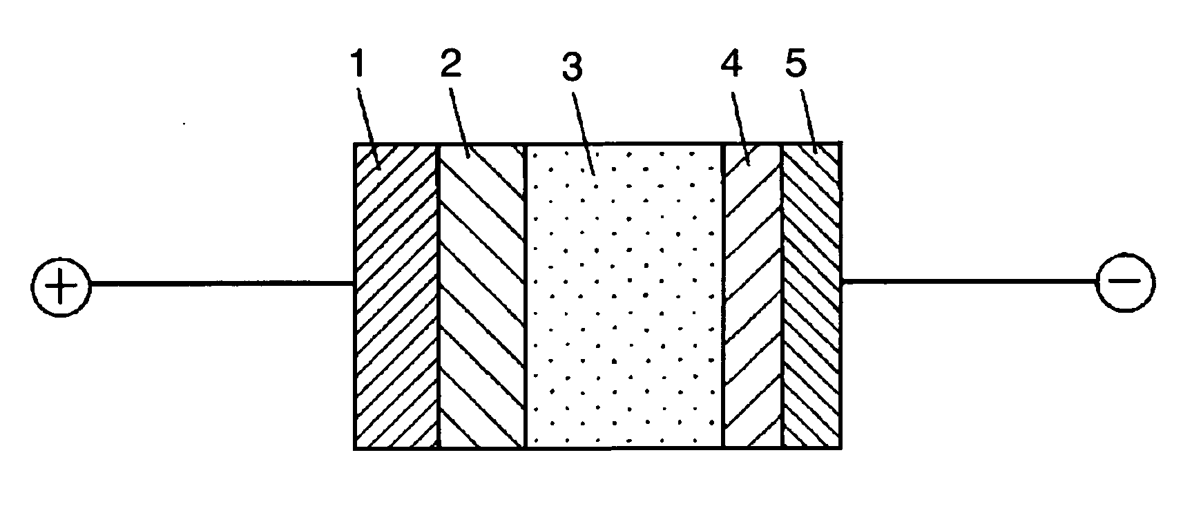
[0062] Etched aluminum foil dimensioned of 3 mm×4 mm attached with a lead wire is used as an anode. Dielectric oxide film 2 is formed on a surface of the etched aluminum foil by dipping the etched aluminum foil into solution involving water containing 3% of ammonium adipate for anodization at 12V and at the solution temperature 70° C. for 60 minutes. After dipping anodized etched aluminum foil 1 in solution involving water containing 30 % manganese nitrate, anodized etched aluminum foil 1 is pulled out of the solution for air drying, and is finally processed for thermal decomposition at 300° C. for 10 minutes to form manganese oxide composing a part of solid electrolyte 3.
[0063] Then, solution involving water for polymerization composed of 0.5 mol / L of ethylenedioxythiophene monomer and 0.1 mol / L of compound (I) (m=2, n=1) is prepared to form the solid electrolyte. A terminal to initiate polymerization is placed close to a surface of the etched aluminum foil to form the solid elect...
example 2
[0065] By the method similar to example 1, the etched aluminum foil is anodized to form dielectric oxide film 2. The anodized etched aluminum foil is immersed in solution involving water containing 5% of water-soluble polyaniline, and is then heat-treated at 200° C. for 10 minutes to form a conductive polymer composing a part of the solid electrolyte 3. Then, solution involving water as solvent for polymerization dissolving a 0.5 mol / L of pyrrole monomer and a 0.1 mol / L of compound (I) (m=2, n=1) is prepared to form the solid electrolyte.
[0066] The solid electrolytic capacitor is prepared under conditions similar to example 1 except the condition of solution involving water as solvent for polymerization.
example 3
[0067] By the method similar to example 1, a manganese oxide film composing a part of the solid electrolyte is formed on a surface of the anodized etched aluminum foil. Then, solution involving ethanol for polymerization dissolving a 0.5 mol / L of ethylenedioxythiophene monomer and a 0.1 mol / L of compound (I) (m=2, n=1) is prepared to form the solid electrolyte.
[0068] The solid electrolytic capacitor is prepared under conditions similar to example 1 except the condition of solution for polymerization.
PUM
| Property | Measurement | Unit |
|---|---|---|
| Electric potential / voltage | aaaaa | aaaaa |
| Substance count | aaaaa | aaaaa |
| Substance count | aaaaa | aaaaa |
Abstract
Description
Claims
Application Information
 - Generate Ideas
- Intellectual Property
- Life Sciences
- Materials
- Tech Scout
- Unparalleled Data Quality
- Higher Quality Content
- 60% Fewer Hallucinations
Browse by: Latest US Patents, China's latest patents, Technical Efficacy Thesaurus, Application Domain, Technology Topic, Popular Technical Reports.
© 2025 PatSnap. All rights reserved.Legal|Privacy policy|Modern Slavery Act Transparency Statement|Sitemap|About US| Contact US: help@patsnap.com