
Methods and apparatus for reducing power dissipation in a multi-processor system

a multi-processor system and power dissipation technology, applied in multi-programming arrangements, instruments, generating/distributing signals, etc., can solve the problems of not being able to generally match the processing speed of multi-processor architectures, applications that require extremely fast processing speeds, and not being entirely satisfactory

Inactive Publication Date: 2005-10-13
SONY COMPUTER ENTERTAINMENT INC
View PDF44 Cites 35 Cited by
  • Summary
  • Abstract
  • Description
  • Claims
  • Application Information

AI Technical Summary

Benefits of technology

[0009] A plurality of the computer systems may be members of a network if desired. The consistent modular structure enables efficient, high speed processing of applications and data by the multi-processor computer system, and if a network is employed, the rapid transmission of applications and data over the network. This structure also simplifies the building of members of the network of various sizes and processing power and the preparation of applications for processing by these members.
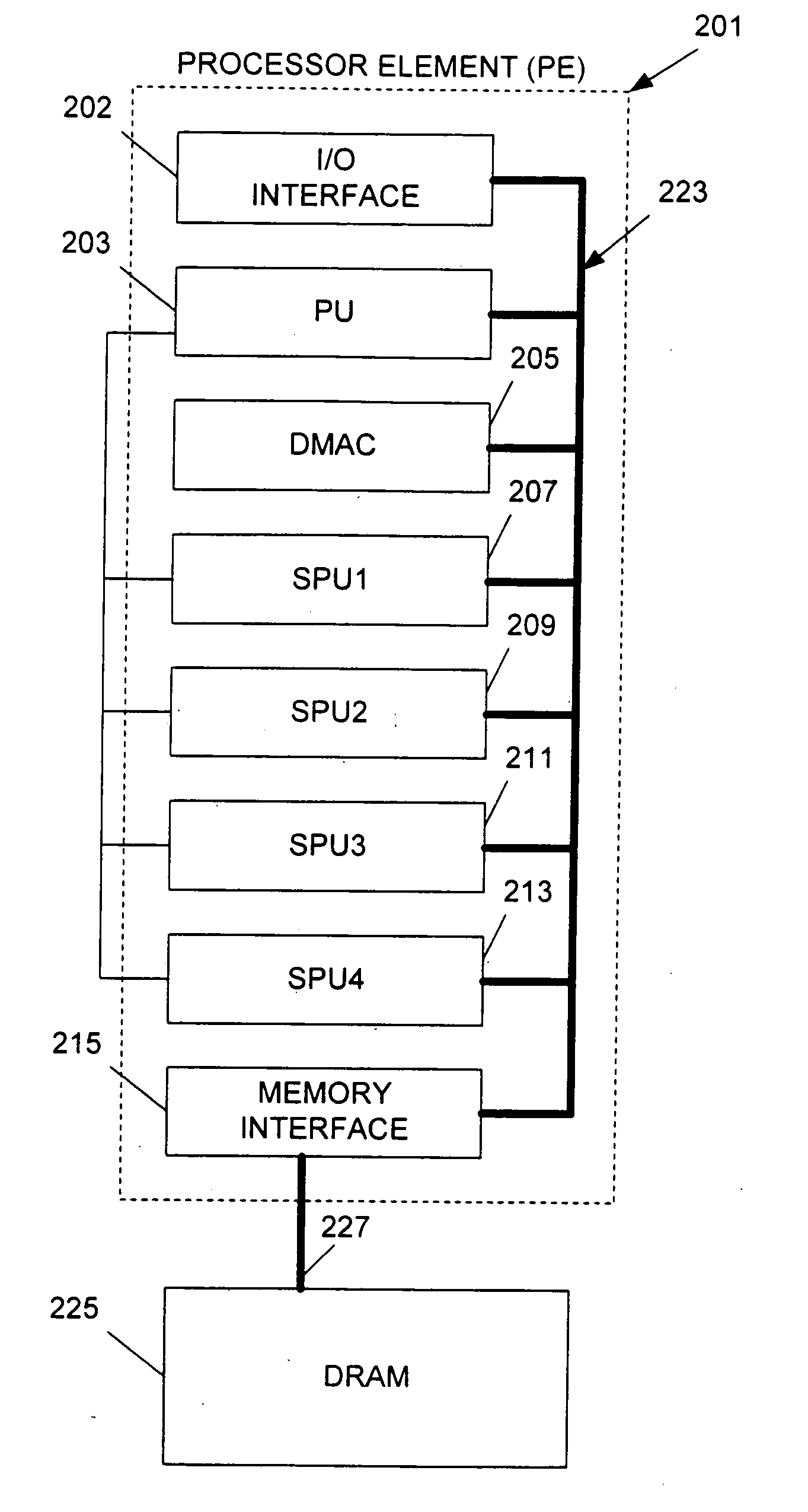
[0014] In accordance with one or more aspects of the present invention, a method includes: monitoring processor tasks and associated processor loads therefor that are allocated to be performed by respective sub-processing units associated with a main processing unit; re-allocating at least some of the tasks based on their associated processor loads such that at least one of the sub-processing units is not scheduled to perform any tasks; and commanding the sub-processing units that are not scheduled to perform any tasks into a low power consumption state.

Problems solved by technology

These applications require extremely fast processing speeds, such as many thousands of megabits of data per second.
While single processing units are capable of fast processing speeds, they cannot generally match the processing speeds of multi-processor architectures.
While mechanical heat management techniques may be employed, they are not entirely satisfactory because they add recurring material and labor costs to the final product.
Mechanical heat management techniques also might not provide sufficient cooling.

Method used


Image

  • Methods and apparatus for reducing power dissipation in a multi-processor system
  • Methods and apparatus for reducing power dissipation in a multi-processor system
  • Methods and apparatus for reducing power dissipation in a multi-processor system

Examples


Embodiment Construction

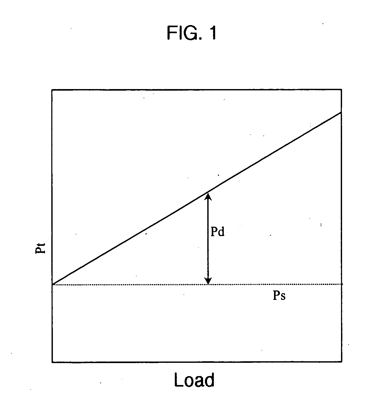
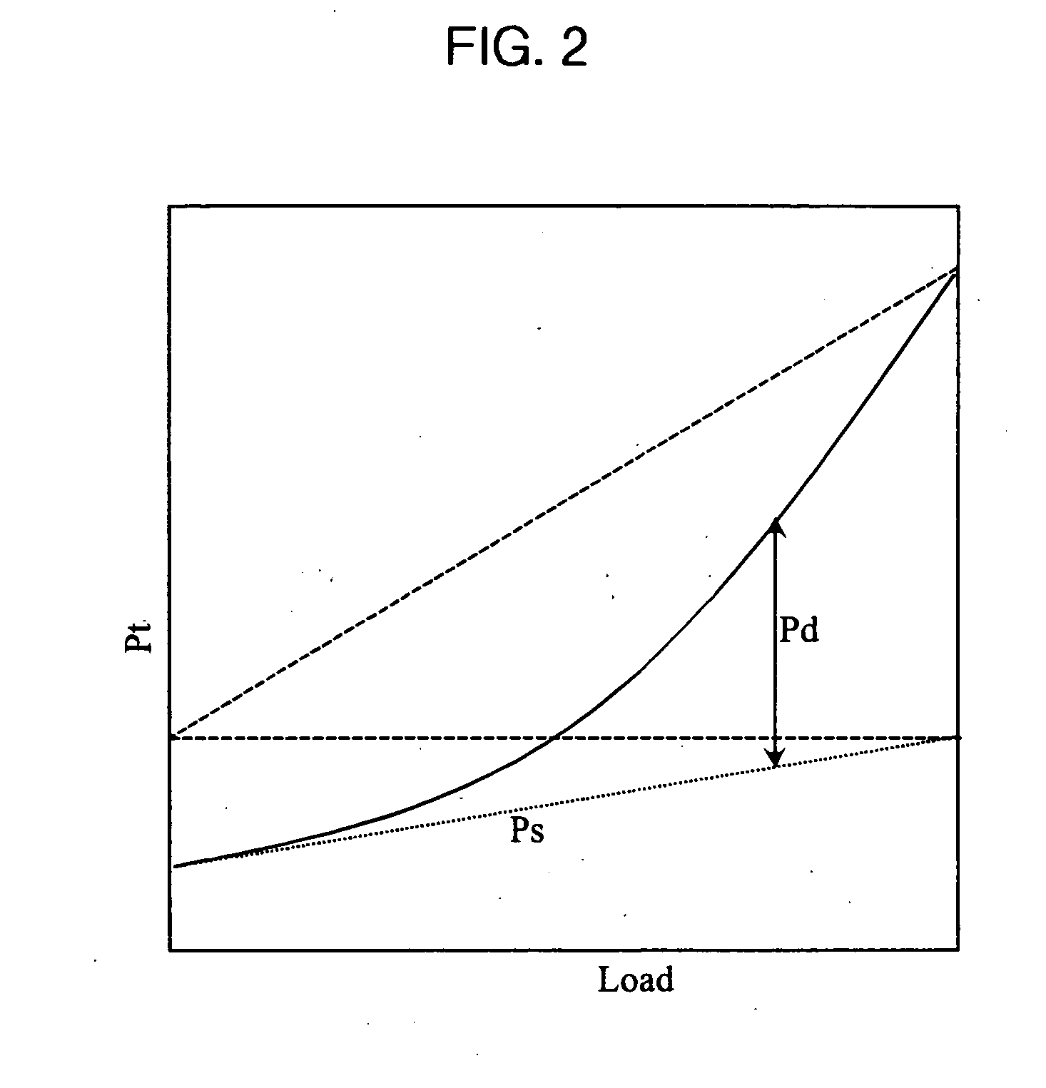
[0035] In order to place the various aspects of the present invention into context, reference is made to the graphical illustration of static power, dynamic power, and total power curves shown in FIG. 1. These power curves are examples of the power characteristics produced by a processing unit as a function of the processing load of such processor.

[0036] The static power Ps is equal to the leakage current, I1, multiplied by the operating voltage, Vdd, of the processing unit, which may be expressed as follows: Ps=I1×Vdd. When the leakage current I1 and the operating voltage Vdd are constant, then the static power Ps is also constant as a function of the processing load of the processor, as is illustrated in FIG. 1. The dynamic power Pd dissipated by the processor may be expressed as follows: Pd=Sf×C×F×Vdd2, where Sf is the processing load of the processor, C is the equivalent capacitance of the processor, F is the clock frequency, and Vdd is the operating voltage. Sf is indicative o...


PUM


Abstract

Methods and apparatus for monitoring processor tasks and associated processor loads therefor that are allocated to be performed by respective sub-processing units associated with a main processing unit; re-allocating at least some of the tasks based on their associated processor loads such that at least one of the sub-processing units is not scheduled to perform any tasks; and commanding the sub-processing units that are not scheduled to perform any tasks into a low power consumption state.

Description

BACKGROUND OF THE INVENTION [0001] The present invention relates to methods and apparatus for reducing power dissipation in a multi-processor system and, in particular, for allocating tasks among multiple processors in the system in order to reduce the overall power dissipated by the multi-processors. [0002] Real-time, multimedia, applications are becoming increasingly important. These applications require extremely fast processing speeds, such as many thousands of megabits of data per second. While single processing units are capable of fast processing speeds, they cannot generally match the processing speeds of multi-processor architectures. Indeed, in multi-processor systems, a plurality of processors can operate in parallel (or at least in concert) to achieve desired processing results. [0003] The types of computers and computing devices that may employ multi-processing techniques are extensive. In addition to personal computers (PCs) and servers, these computing devices include...

Claims


Application Information

Patent Timeline
IPC IPC(8): G06F1/32G06F1/04G06F9/40G06F9/50G06F15/76
CPCY02B60/144G06F1/329Y02B60/1282G06F9/5088Y02B60/1278Y02B60/162G06F1/3287G06F1/3228Y02D10/00G06F1/32G06F9/50
Inventor HIRAIRI, KOJI
Owner SONY COMPUTER ENTERTAINMENT INC
Learn More